Cirkit Designer
Your all-in-one circuit design IDE
Home /
Project Documentation
Arduino Nano-Controlled Servo System with Dual HX711 Load Sensors

Circuit Documentation
Summary of the Circuit
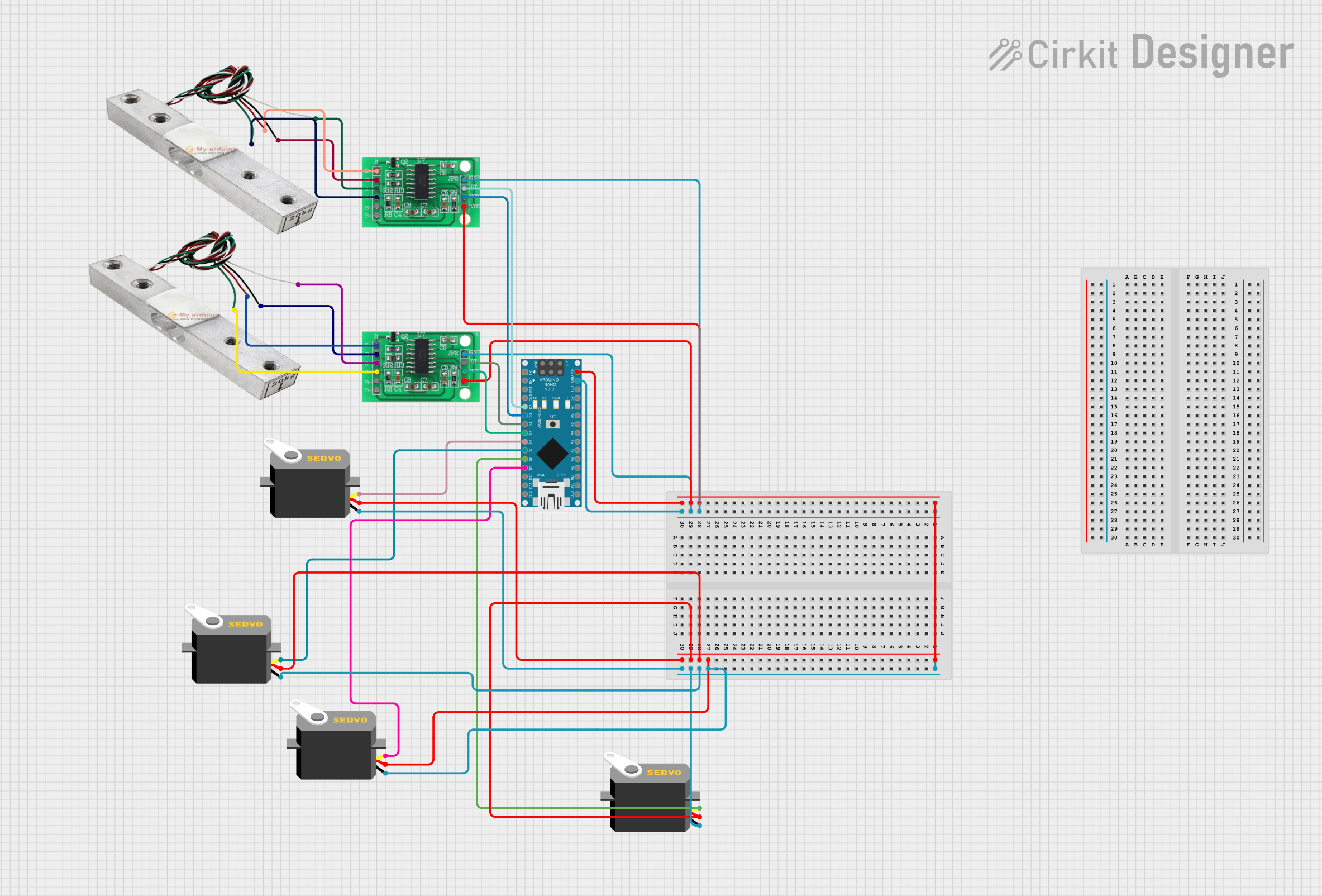
This circuit is designed to interface an Arduino Nano with multiple servo motors and two HX711 Bridge Sensor Interfaces, which are connected to load cells. The Arduino Nano serves as the central processing unit, controlling the servo motors based on the data received from the HX711 modules, which are used to measure weight or force through the load cells. The servos are powered directly from the Arduino's voltage input, and the HX711 modules are powered through the 3.3/3.5V supply pins. Communication between the Arduino and the HX711 modules is established via digital pins D2-D5, while the servo motors are controlled through pins D6-D9.
Component List
Arduino Nano
- Microcontroller board based on the ATmega328P
- Pins: D1/TX, D0/RX, RESET, GND, D2-D13/SCK, VIN, 5V, A0-A7, AREF, 3V3
HX711 - Bridge Sensor Interface (2 units)
- Precision 24-bit analog-to-digital converter (ADC) designed for weigh scales and industrial control applications to interface directly with a bridge sensor
- Pins: E+, E-, A-, A+, B-, B+, GND - GROUND, DATA (OUT), SCK - CLOCK (IN), 3.3/3.5V Supply
Load Cell (2 units)
- A transducer that converts force into an electrical signal
- Pins: wire1, wire2, wire3, wire4
Servo Motors (4 units)
- Rotary actuators that allow for precise control of angular position
- Pins: gnd, vcc, pulse
Wiring Details
Arduino Nano
- VIN connected to the VCC of all Servo Motors and the 3.3/3.5V Supply of both HX711 modules
- GND connected to the GND of all Servo Motors and the GND - GROUND of both HX711 modules
- D2 connected to DATA (OUT) of one HX711 module
- D3 connected to SCK - CLOCK (IN) of the same HX711 module
- D4 connected to DATA (OUT) of the other HX711 module
- D5 connected to SCK - CLOCK (IN) of the other HX711 module
- D6-D9 connected to the pulse pins of the four Servo Motors
HX711 - Bridge Sensor Interface
- E+ and E- connected to the corresponding wires of the Load Cells
- A- and A+ connected to the other two wires of the Load Cells
- DATA (OUT) and SCK - CLOCK (IN) connected to the Arduino Nano
Load Cell
- wire1 and wire2 connected to A- and A+ of the corresponding HX711 module
- wire3 and wire4 connected to E+ and E- of the corresponding HX711 module
Servo Motors
- vcc connected to VIN of the Arduino Nano
- gnd connected to GND of the Arduino Nano
- pulse connected to D6-D9 of the Arduino Nano
Documented Code
Arduino Nano Code (sketch.ino)
void setup() {
  // put your setup code here, to run once:

}

void loop() {
  // put your main code here, to run repeatedly:

}
Additional Notes (documentation.txt)
No additional code documentation was provided for this file.