
Arduino-Based Egg Incubator with DHT22, LCD Display, and Stepper Motor
View and Edit Project In Cirkit Designer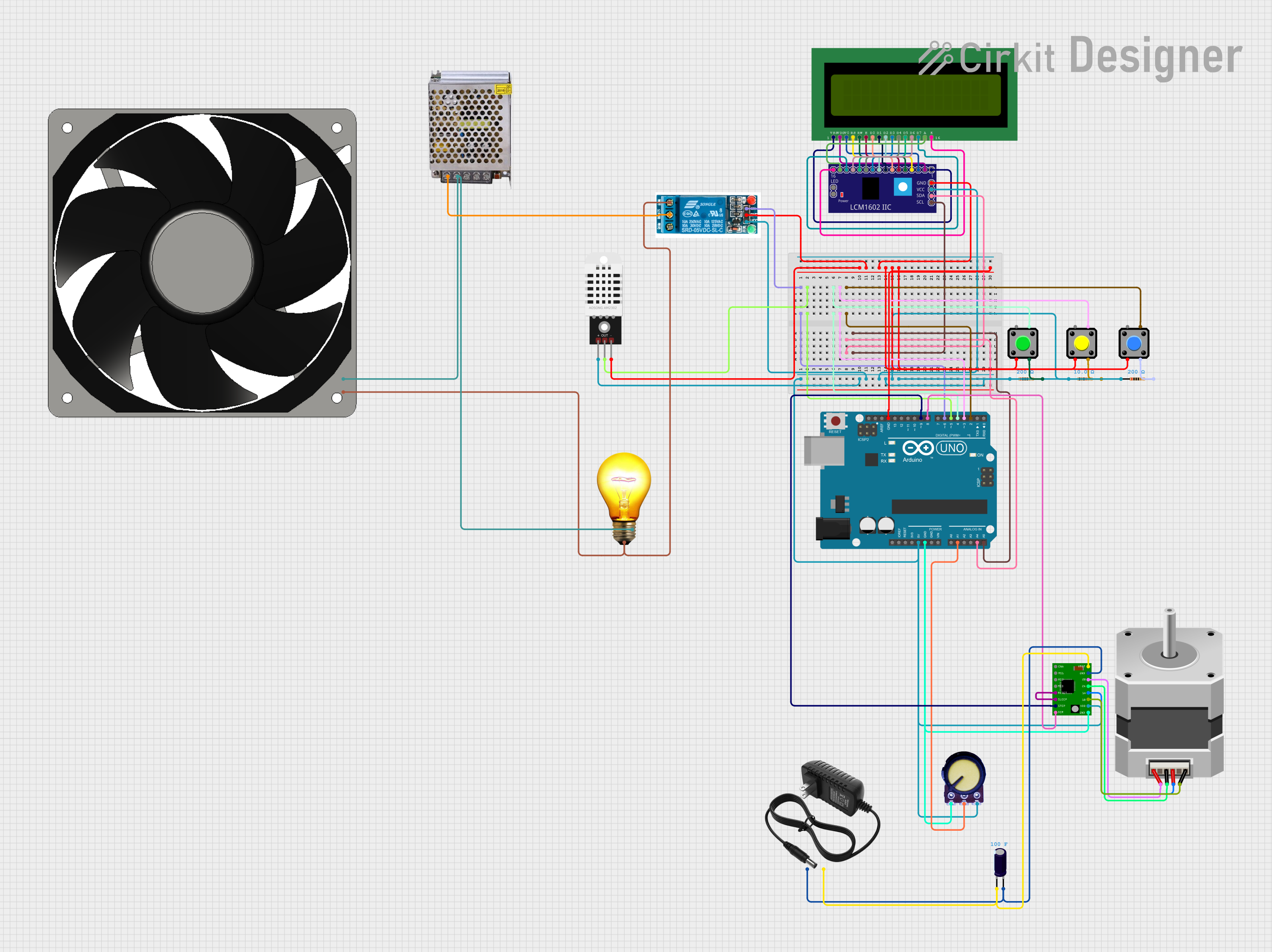
Circuit Documentation
Summary
This project is an egg incubator system using an Arduino UNO. The system includes a DHT22 sensor to read temperature, an LCD 16x2 display to show temperature and heater status, a relay to control the heater, a stepper motor to rotate the eggs, a potentiometer to adjust the stepper motor speed, and pushbuttons to increase/decrease the target temperature and manually control the heater.
Component List
DHT22
- Description: Temperature and humidity sensor
- Pins: +, Out, -
5V Relay
- Description: Relay module for switching
- Pins: Normally Open, Common terminal, Normally Closed, In, GND, VCC
LCD 16x2 (Wokwi Compatible)
- Description: 16x2 character LCD display
- Pins: VSS, VDD, V0, RS, RW, E, D0, D1, D2, D3, D4, D5, D6, D7, A, K
LCM1602 IIC
- Description: I2C interface for LCD
- Pins: GND, VCC, SDA, SCL, D6, D7, A, K, VSS, VDD, V0, RS, D2, D3, D4, D5, RW, E, D0, D1, LED_A, LED_B
Pushbutton
- Description: Momentary pushbutton switch
- Pins: Pin 2, Pin 1, Pin 3, Pin 4
Resistor (10 Ohms)
- Description: Resistor with 10 Ohms resistance
- Pins: pin1, pin2
AC Bulb
- Description: AC light bulb
- Pins: P, N
Power Supply 12V 5AMP
- Description: Power supply unit
- Pins: 220V Positive Pole (AC), 220V Negative Pole (AC), GND, GND (DC), 12V-24V Output (DC)
120 Fan 12V
- Description: 12V cooling fan
- Pins: 12V+, GND
Resistor (200 Ohms)
- Description: Resistor with 200 Ohms resistance
- Pins: pin1, pin2
Arduino UNO
- Description: Microcontroller board
- Pins: UNUSED, IOREF, Reset, 3.3V, 5V, GND, Vin, A0, A1, A2, A3, A4, A5, SCL, SDA, AREF, D13, D12, D11, D10, D9, D8, D7, D6, D5, D4, D3, D2, D1, D0
Stepper Motor (Bipolar)
- Description: Bipolar stepper motor
- Pins: D, B, C, A
A4988 Stepper Motor Driver Carrier
- Description: Stepper motor driver
- Pins: ENABLE, MS1, MS2, MS3, RESET, SLEEP, STEP, DIR, GND, VCC, 1B, 1A, 2A, 2B, VMOT
Potentiometer
- Description: Variable resistor
- Pins: GND, Output, VCC
Electrolytic Capacitor
- Description: Capacitor with 100 Farads capacitance
- Pins: -, +
12V Power Supply
- Description: 12V power supply unit
- Pins: +, -
Wiring Details
DHT22
- +: Connected to Arduino UNO 5V
- Out: Connected to Arduino UNO D5
- -: Connected to GND
5V Relay
- In: Connected to Arduino UNO D6
- GND: Connected to GND
- VCC: Connected to Arduino UNO 5V
- Normally Open: Connected to 120 Fan 12V GND and AC Bulb P
- Common terminal: Connected to Power Supply 12V 5AMP 220V Positive Pole (AC)
LCD 16x2 (Wokwi Compatible)
- VSS: Connected to LCM1602 IIC VSS
- VDD: Connected to LCM1602 IIC VDD
- V0: Connected to LCM1602 IIC V0
- RS: Connected to LCM1602 IIC RS
- RW: Connected to LCM1602 IIC RW
- E: Connected to LCM1602 IIC E
- D0: Connected to LCM1602 IIC D0
- D1: Connected to LCM1602 IIC D1
- D2: Connected to LCM1602 IIC D2
- D3: Connected to LCM1602 IIC D3
- D4: Connected to LCM1602 IIC D4
- D5: Connected to LCM1602 IIC D5
- D6: Connected to LCM1602 IIC D6
- D7: Connected to LCM1602 IIC D7
- A: Connected to LCM1602 IIC A
- K: Connected to LCM1602 IIC K
LCM1602 IIC
- GND: Connected to GND
- VCC: Connected to Arduino UNO 5V
- SDA: Connected to Arduino UNO A4
- SCL: Connected to Arduino UNO A5
Pushbutton (Button 1)
- Pin 2: Connected to GND
- Pin 4: Connected to Arduino UNO D4
- Pin 3: Connected to Resistor (200 Ohms) pin2
Pushbutton (Button 2)
- Pin 2: Connected to GND
- Pin 4: Connected to Arduino UNO D3
- Pin 3: Connected to Resistor (200 Ohms) pin2
Pushbutton (Button 3)
- Pin 2: Connected to GND
- Pin 4: Connected to Arduino UNO D2
- Pin 3: Connected to Resistor (200 Ohms) pin2
Resistor (10 Ohms)
- pin1: Connected to Arduino UNO 5V
- pin2: Connected to Pushbutton (Button 1) Pin 3
Resistor (200 Ohms)
- pin1: Connected to Arduino UNO 5V
- pin2: Connected to Pushbutton (Button 2) Pin 3
Resistor (200 Ohms)
- pin1: Connected to Arduino UNO 5V
- pin2: Connected to Pushbutton (Button 3) Pin 3
AC Bulb
- P: Connected to 5V Relay Normally Open
- N: Connected to 120 Fan 12V 12V+ and Power Supply 12V 5AMP 220V Negative Pole (AC)
Power Supply 12V 5AMP
- 220V Positive Pole (AC): Connected to 5V Relay Common terminal
- 220V Negative Pole (AC): Connected to AC Bulb N and 120 Fan 12V 12V+
120 Fan 12V
- 12V+: Connected to AC Bulb N and Power Supply 12V 5AMP 220V Negative Pole (AC)
- GND: Connected to 5V Relay Normally Open
Arduino UNO
- D6: Connected to 5V Relay In
- D5: Connected to DHT22 Out
- D4: Connected to Pushbutton (Button 1) Pin 4
- D3: Connected to Pushbutton (Button 2) Pin 4
- A4: Connected to LCM1602 IIC SDA
- D2: Connected to Pushbutton (Button 3) Pin 4
- A5: Connected to LCM1602 IIC SCL
- 5V: Connected to A4988 Stepper Motor Driver Carrier VCC, Potentiometer VCC, DHT22 +, 5V Relay VCC, LCM1602 IIC VCC, Resistor (10 Ohms) pin1, Resistor (200 Ohms) pin1, Resistor (200 Ohms) pin1
- GND: Connected