Cirkit Designer
Your all-in-one circuit design IDE
Home /
Project Documentation
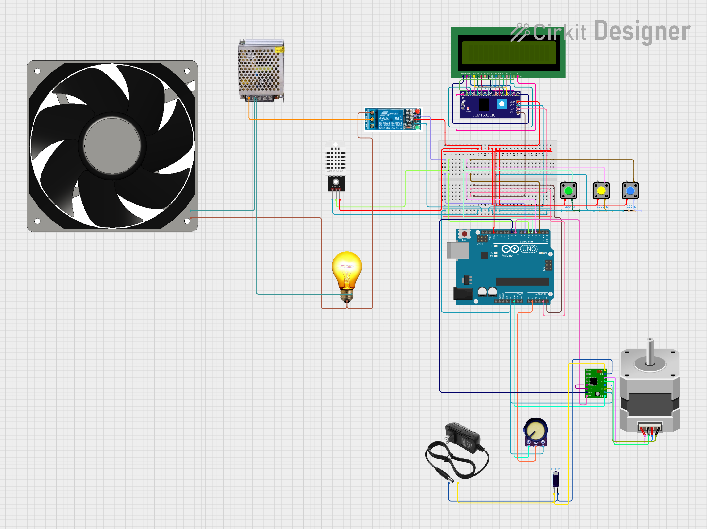
Arduino-Based Egg Incubator with DHT22, LCD Display, and Stepper Motor
Circuit Documentation
Summary
This project is an egg incubator system using an Arduino UNO. The system includes a DHT22 sensor to read temperature, an LCD 16x2 display to show temperature and heater status, a relay to control the heater, a stepper motor to rotate the eggs, a potentiometer to adjust the stepper motor speed, and pushbuttons to increase/decrease the target temperature and manually control the heater.
Component List
DHT22
- Description: Temperature and humidity sensor
- Pins: +, Out, -
5V Relay
- Description: Relay module for switching
- Pins: Normally Open, Common terminal, Normally Closed, In, GND, VCC
LCD 16x2 (Wokwi Compatible)
- Description: 16x2 character LCD display
- Pins: VSS, VDD, V0, RS, RW, E, D0, D1, D2, D3, D4, D5, D6, D7, A, K
LCM1602 IIC
- Description: I2C interface for LCD
- Pins: GND, VCC, SDA, SCL, D6, D7, A, K, VSS, VDD, V0, RS, D2, D3, D4, D5, RW, E, D0, D1, LED_A, LED_B
Pushbutton
- Description: Momentary pushbutton switch
- Pins: Pin 2, Pin 1, Pin 3, Pin 4
Resistor (10 Ohms)
- Description: Resistor with 10 Ohms resistance
- Pins: pin1, pin2
AC Bulb
- Description: AC light bulb
- Pins: P, N
Power Supply 12V 5AMP
- Description: Power supply unit
- Pins: 220V Positive Pole (AC), 220V Negative Pole (AC), GND, GND (DC), 12V-24V Output (DC)
120 Fan 12V
- Description: 12V cooling fan
- Pins: 12V+, GND
Resistor (200 Ohms)
- Description: Resistor with 200 Ohms resistance
- Pins: pin1, pin2
Arduino UNO
- Description: Microcontroller board
- Pins: UNUSED, IOREF, Reset, 3.3V, 5V, GND, Vin, A0, A1, A2, A3, A4, A5, SCL, SDA, AREF, D13, D12, D11, D10, D9, D8, D7, D6, D5, D4, D3, D2, D1, D0
Stepper Motor (Bipolar)
- Description: Bipolar stepper motor
- Pins: D, B, C, A
A4988 Stepper Motor Driver Carrier
- Description: Stepper motor driver
- Pins: ENABLE, MS1, MS2, MS3, RESET, SLEEP, STEP, DIR, GND, VCC, 1B, 1A, 2A, 2B, VMOT
Potentiometer
- Description: Variable resistor
- Pins: GND, Output, VCC
Electrolytic Capacitor
- Description: Capacitor with 100 Farads capacitance
- Pins: -, +
12V Power Supply
- Description: 12V power supply unit
- Pins: +, -
Wiring Details
DHT22
- +: Connected to Arduino UNO 5V
- Out: Connected to Arduino UNO D5
- -: Connected to GND
5V Relay
- In: Connected to Arduino UNO D6
- GND: Connected to GND
- VCC: Connected to Arduino UNO 5V
- Normally Open: Connected to 120 Fan 12V GND and AC Bulb P
- Common terminal: Connected to Power Supply 12V 5AMP 220V Positive Pole (AC)
LCD 16x2 (Wokwi Compatible)
- VSS: Connected to LCM1602 IIC VSS
- VDD: Connected to LCM1602 IIC VDD
- V0: Connected to LCM1602 IIC V0
- RS: Connected to LCM1602 IIC RS
- RW: Connected to LCM1602 IIC RW
- E: Connected to LCM1602 IIC E
- D0: Connected to LCM1602 IIC D0
- D1: Connected to LCM1602 IIC D1
- D2: Connected to LCM1602 IIC D2
- D3: Connected to LCM1602 IIC D3
- D4: Connected to LCM1602 IIC D4
- D5: Connected to LCM1602 IIC D5
- D6: Connected to LCM1602 IIC D6
- D7: Connected to LCM1602 IIC D7
- A: Connected to LCM1602 IIC A
- K: Connected to LCM1602 IIC K
LCM1602 IIC
- GND: Connected to GND
- VCC: Connected to Arduino UNO 5V
- SDA: Connected to Arduino UNO A4
- SCL: Connected to Arduino UNO A5
Pushbutton (Button 1)
- Pin 2: Connected to GND
- Pin 4: Connected to Arduino UNO D4
- Pin 3: Connected to Resistor (200 Ohms) pin2
Pushbutton (Button 2)
- Pin 2: Connected to GND
- Pin 4: Connected to Arduino UNO D3
- Pin 3: Connected to Resistor (200 Ohms) pin2
Pushbutton (Button 3)
- Pin 2: Connected to GND
- Pin 4: Connected to Arduino UNO D2
- Pin 3: Connected to Resistor (200 Ohms) pin2
Resistor (10 Ohms)
- pin1: Connected to Arduino UNO 5V
- pin2: Connected to Pushbutton (Button 1) Pin 3
Resistor (200 Ohms)
- pin1: Connected to Arduino UNO 5V
- pin2: Connected to Pushbutton (Button 2) Pin 3
Resistor (200 Ohms)
- pin1: Connected to Arduino UNO 5V
- pin2: Connected to Pushbutton (Button 3) Pin 3
AC Bulb
- P: Connected to 5V Relay Normally Open
- N: Connected to 120 Fan 12V 12V+ and Power Supply 12V 5AMP 220V Negative Pole (AC)
Power Supply 12V 5AMP
- 220V Positive Pole (AC): Connected to 5V Relay Common terminal
- 220V Negative Pole (AC): Connected to AC Bulb N and 120 Fan 12V 12V+
120 Fan 12V
- 12V+: Connected to AC Bulb N and Power Supply 12V 5AMP 220V Negative Pole (AC)
- GND: Connected to 5V Relay Normally Open
Arduino UNO
- D6: Connected to 5V Relay In
- D5: Connected to DHT22 Out
- D4: Connected to Pushbutton (Button 1) Pin 4
- D3: Connected to Pushbutton (Button 2) Pin 4
- A4: Connected to LCM1602 IIC SDA
- D2: Connected to Pushbutton (Button 3) Pin 4
- A5: Connected to LCM1602 IIC SCL
- 5V: Connected to A4988 Stepper Motor Driver Carrier VCC, Potentiometer VCC, DHT22 +, 5V Relay VCC, LCM1602 IIC VCC, Resistor (10 Ohms) pin1, Resistor (200 Ohms) pin1, Resistor (200 Ohms) pin1
- GND: Connected