
ESP32-Based Multi-Sensor Health and Navigation Tracker with Battery Management
View and Edit Project In Cirkit Designer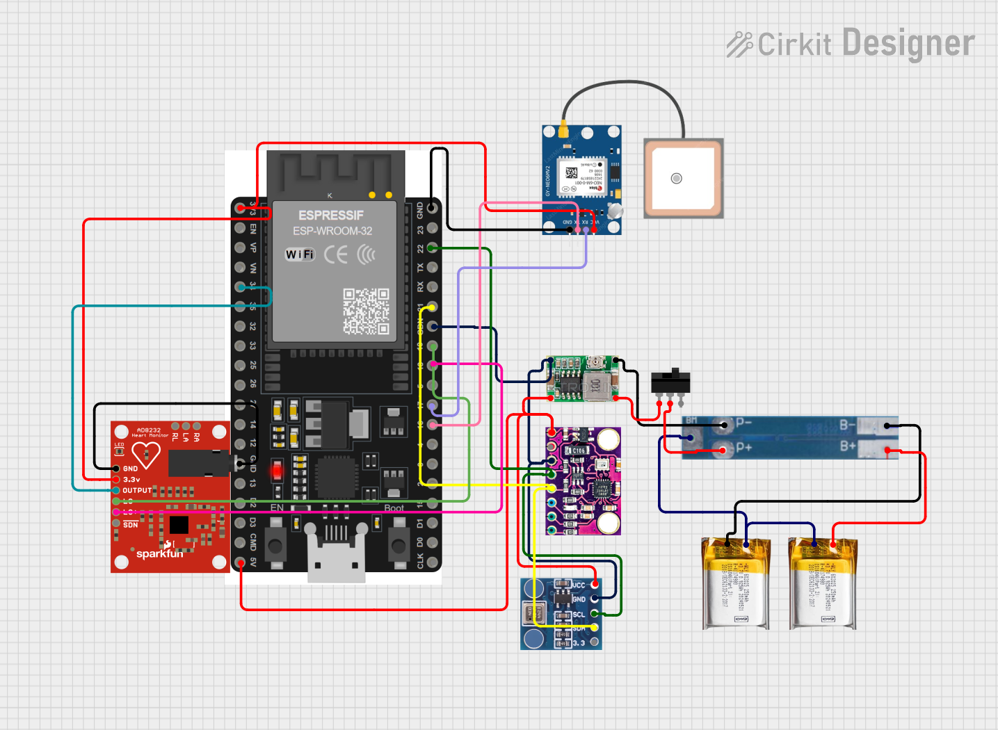
Circuit Documentation
Summary
This document provides a detailed overview of a circuit designed to integrate various sensors and modules with an ESP32 microcontroller. The circuit includes a GPS module, a heart rate monitor, a barometric pressure sensor, a 9-axis motion sensor, a battery management system (BMS), a power supply module, and a toggle switch for power control. The ESP32 serves as the central processing unit, interfacing with the sensors and modules to collect data and possibly provide navigational and health monitoring capabilities.
Component List
ESP32 38 PINS
- Description: A microcontroller with Wi-Fi and Bluetooth capabilities, featuring a wide range of GPIO pins.
- Pins: GND, 23, 22/SCL, 1, 2, 21/SDA, 19, 18, 5, 17/TX2, 16/RX2, 4, 0, 15, D1, D0, CLK, 3V3, EN, VP, VN, 34, 35, 32, 33, 25, 26, 27, 14, 12, 13, D2, D3, 11, 5V/VIN
AD8232 Heart Rate Monitor
- Description: A single-lead heart rate monitor for wearable health monitoring applications.
- Pins: GND, 3.3v, OUTPUT, LO-, LO+, SDN, RA, LA, RL
BMP180
- Description: A digital barometric pressure sensor with high accuracy and low power consumption.
- Pins: 3.3, SDA, SCL, GND, VCC
MPU9250/GY-91
- Description: A 9-axis motion sensor with a 3-axis gyroscope, 3-axis accelerometer, and 3-axis magnetometer.
- Pins: 3V3, GND, SCL, SDA, VIN/5V
2S BMS
- Description: A battery management system for 2-series lithium-polymer batteries, providing overcharge, over-discharge, and short-circuit protection.
- Pins: P-, P+, BM, B-, B+
GPS NEO 6M
- Description: A GPS module capable of providing accurate geographical location data.
- Pins: VCC, RX, TX, GND
3.7v LiPo Battery
- Description: A lithium-polymer battery providing a power source for the circuit.
- Pins: +Ve, GND
Mini 360 Buck Converter
- Description: A DC-DC step-down (buck) converter module used to regulate voltage levels in the circuit.
- Pins: IN-, OUT-, OUT+, IN+
Toggle Switch
- Description: A switch used to control the power supply to the circuit.
- Pins: L1, COM, L2
Wiring Details
ESP32 38 PINS
- GND connected to GPS NEO 6M GND, MPU9250/GY-91 GND, BMP180 GND, AD8232 Heart Rate Monitor GND
- 22/SCL connected to MPU9250/GY-91 SCL, BMP180 SCL
- 21/SDA connected to MPU9250/GY-91 SDA, BMP180 SDA
- 19 connected to AD8232 Heart Rate Monitor LO-
- 18 connected to AD8232 Heart Rate Monitor LO+
- 17/TX2 connected to GPS NEO 6M RX
- 16/RX2 connected to GPS NEO 6M TX
- 3V3 connected to GPS NEO 6M VCC, AD8232 Heart Rate Monitor 3.3v
- 34 connected to AD8232 Heart Rate Monitor OUTPUT
- 5V/VIN connected to MPU9250/GY-91 VIN/5V, BMP180 VCC
AD8232 Heart Rate Monitor
- GND connected to ESP32 GND
- 3.3v connected to ESP32 3V3
- OUTPUT connected to ESP32 34
- LO- connected to ESP32 19
- LO+ connected to ESP32 18
BMP180
- 3.3 connected to ESP32 3V3
- SDA connected to ESP32 21/SDA
- SCL connected to ESP32 22/SCL
- GND connected to ESP32 GND
- VCC connected to ESP32 5V/VIN
MPU9250/GY-91
- 3V3 connected to ESP32 3V3
- GND connected to ESP32 GND
- SCL connected to ESP32 22/SCL
- SDA connected to ESP32 21/SDA
- VIN/5V connected to ESP32 5V/VIN
2S BMS
- P- connected to Mini 360 Buck Converter OUT-
- P+ connected to Toggle Switch COM
- BM connected to 3.7v LiPo +Ve
- B- connected to 3.7v LiPo GND
- B+ connected to 3.7v LiPo +Ve
GPS NEO 6M
- VCC connected to ESP32 3V3
- RX connected to ESP32 17/TX2
- TX connected to ESP32 16/RX2
- GND connected to ESP32 GND
Mini 360 Buck Converter
- IN- connected to ESP32 GND
- OUT- connected to 2S BMS P-
- OUT+ connected to Toggle Switch L1
- IN+ connected to ESP32 5V/VIN
Toggle Switch
- L1 connected to Mini 360 Buck Converter OUT+
- COM connected to 2S BMS P+
Documented Code
Since no code was provided for the microcontroller, this section is currently empty. When code is available, it should be documented here with explanations of its functionality and how it interacts with the connected components.
This documentation provides an overview of the circuit's components and their interconnections. It is intended to assist in understanding, maintaining, and troubleshooting the circuit. Further details, such as schematics and code implementation, would complete the documentation when available.