
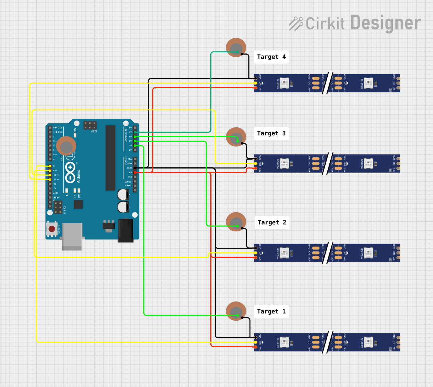
Circuit Documentation
Summary
This circuit is designed to interface an Arduino UNO with multiple WS2812 RGB LED strips and Piezo sensors. The Arduino UNO controls the LED strips and reads signals from the Piezo sensors. The LED strips are individually addressable, allowing for complex lighting effects, while the Piezo sensors can detect vibrations or pressure, which can be used for interactive applications. The circuit is powered by the 5V output from the Arduino UNO, and all components share a common ground.
Component List
Arduino UNO
- Microcontroller board based on the ATmega328P
- It has 14 digital input/output pins, 6 analog inputs, a 16 MHz quartz crystal, a USB connection, a power jack, an ICSP header, and a reset button.
WS2812 RGB LED Strip
- An addressable LED strip with integrated WS2812 control ICs.
- Each LED can be individually controlled with a digital signal.
Piezo Sensor
- A sensor that generates an electrical charge in response to applied mechanical stress (vibration or pressure).
Comment
- A non-electrical component used for annotations or notes within the circuit design.
Wiring Details
Arduino UNO
- 5V: Powers the WS2812 RGB LED strips.
- GND: Common ground for the circuit.
- A1 - A4: Analog inputs connected to the Piezo sensors.
- D8 - D11: Digital outputs controlling the data input pins of the WS2812 RGB LED strips.
WS2812 RGB LED Strip
- DIN: Data input pin connected to a digital output on the Arduino UNO.
- 5V: Power input pin connected to the 5V output on the Arduino UNO.
- GND: Ground pin connected to the common ground.
Piezo Sensor
- +: Positive pin connected to an analog input on the Arduino UNO.
- -: Negative pin connected to the common ground.
Documented Code
/*Piezo sensor with arduino.
 5 Target system with multiple Game Modes
*/

#include <Arduino.h>
#include <TM1637Display.h>
#include <SPI.h>

#include <Adafruit_NeoPixel.h>

//Setup each of the 5 targets
#define PINledstrip1 8  //ControlStatus LED strip on D10 OR RingLED
#define sensor1 A1
#define PINledstrip2 9
#define sensor2 A2
#define PINledstrip3 10  //ControlStatus LED strip on D10 OR RingLED
#define sensor3 A3
#define PINledstrip4 11
#define sensor4 A4
#define PINledstrip5 12  //ControlStatus LED strip on D10 OR RingLED
#define sensor5 A5

#define cBlack pixels1.Color(0, 0, 0)       // Black/OFF
#define cWhite pixels1.Color(255,255,255)   // White
#define cGreen pixels1.Color(0, 255, 0)     // Green
#define cRed pixels1.Color(255, 0, 0)       // Red
#define cBlue pixels1.Color(0,0,255)        // Blue
#define cYellow pixels1.Color(255,255,0)    // Yellow

#define NUMPIXELS 60
Adafruit_NeoPixel pixels1(NUMPIXELS, PINledstrip1, NEO_GRB + NEO_KHZ800);
Adafruit_NeoPixel pixels2(NUMPIXELS, PINledstrip2, NEO_GRB + NEO_KHZ800);
Adafruit_NeoPixel pixels3(NUMPIXELS, PINledstrip3, NEO_GRB + NEO_KHZ800);
Adafruit_NeoPixel pixels4(NUMPIXELS, PINledstrip4, NEO_GRB + NEO_KHZ800);
Adafruit_NeoPixel pixels5(NUMPIXELS, PINledstrip5, NEO_GRB + NEO_KHZ800);

int targetNum = 0;

void setup() {
  Serial.begin(9600);  //enable serial monitor

  pinMode(PINledstrip1, OUTPUT);
  pinMode(PINledstrip2, OUTPUT);
  pinMode(PINledstrip3, OUTPUT);
  pinMode(PINledstrip4, OUTPUT);
  pinMode(PINledstrip5, OUTPUT);

  pixels1.begin();
  pixels2.begin();
  pixels3.begin();
  pixels4.begin();
  pixels5.begin();

  //Test Game Modes here
}

void loop() {
  targetNum = random(1, 5); //target count +1

  resetALLLED(0);                //turn off LEDs
  colorWipe(cBlack, targetNum);  // black
                                 //resetALLLED(0);  //OFF
  Serial.println("OFF");
  delay(2000);

  colorWipe(cWhite, targetNum);  // White
                                 //resetALLLED(3);  //WHITE
  Serial.println("WHITE");
  delay(2000);

  colorWipe(cRed, targetNum);  // Red
  //resetALLLED(1);  //RED
  Serial.println("RED");
  delay(2000);

  colorWipe(cGreen, targetNum);  // Green
  //resetALLLED(4);  //GREEN
  Serial.println("GREEN");
  delay(2000);
}

void colorWipe(uint32_t c, int targetNum) {

  switch (targetNum) {

    case 1:
      Serial.println("Taget 1");
      for (uint16_t i = 0; i < pixels1.numPixels(); i++) {
        pixels1.setPixelColor(i, c);
      }
      pixels1.show();
      break;

    case 2:
      Serial.println("Taget 2");
      for (uint16_t i = 0; i < pixels2.numPixels(); i++) {
        pixels2.setPixelColor(i, c);
      }
      pixels2.show();
      break;

    case 3:
      Serial.println("Taget 3");
      for (uint16_t i = 0; i < pixels3.numPixels(); i++) {
        pixels3.setPixelColor(i, c);
      }
      pixels3.show();
      break;

    case 4:
      Serial.println("Taget 4");
      for (uint16_t i = 0; i < pixels4.numPixels(); i++) {
        pixels4.setPixelColor(i, c);
      }
      pixels4.show();
      break;

    case 5:
      Serial.println("Taget 5");
      for (uint16_t i = 0; i < pixels5.numPixels(); i++) {
        pixels5.setPixelColor(i, c);
      }
      pixels5.show();
      break;
  }
}
This code is designed to control a series of WS2812 RGB LED strips in response to input from Piezo sensors. The Arduino UNO reads the analog signals from the Piezo sensors and drives the LED strips to display various colors. The code includes functions for initializing the LED strips, setting their color, and a main loop that cycles through different colors for demonstration purposes.