
Circuit Documentation
Summary
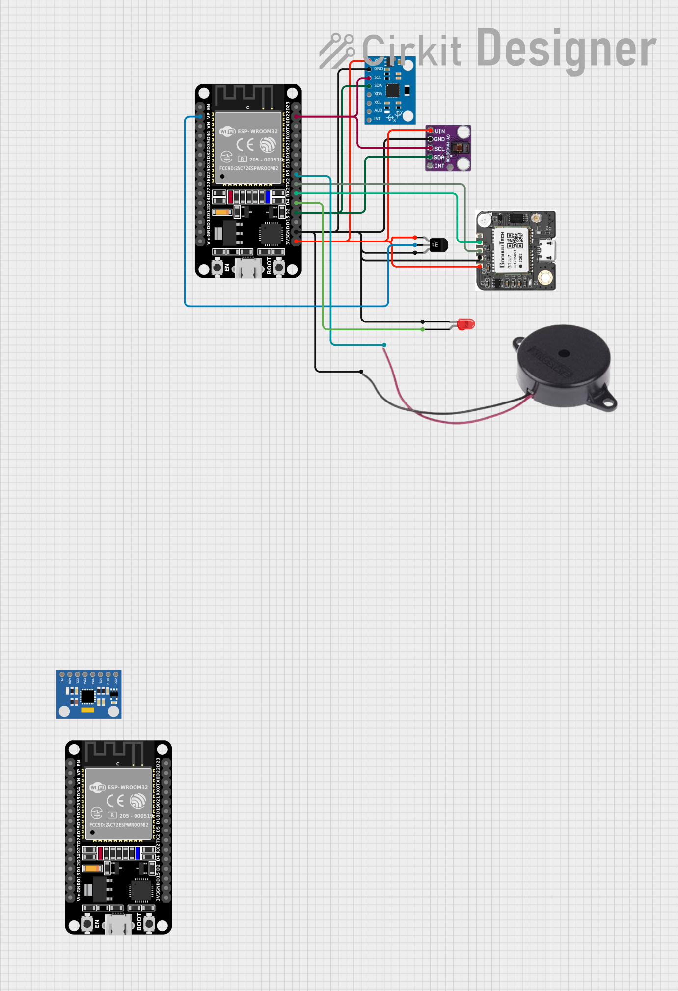
The circuit in question is designed to interface various sensors and modules with an ESP32 microcontroller for the purpose of data acquisition and processing. The sensors include an MPU6050 accelerometer and gyroscope, a MAX30100 pulse oximeter and heart-rate sensor, a temperature sensor (LM35), and a NEO-6M GPS module. The circuit also includes a buzzer and an LED for user interaction. The ESP32 is responsible for reading data from the sensors, processing it, and potentially sending it to an external system or displaying it. The circuit is powered by a 3.3V supply, which is distributed to the sensors and modules that require it.
Component List
- ESP32 (30 pin): A microcontroller with WiFi and Bluetooth capabilities, featuring a wide range of GPIO pins for interfacing with various sensors and peripherals.
- MPU6050 Accelerometer + Gyroscope (Wokwi Compatible): A motion tracking device that measures acceleration and angular velocity along three axes.
- MPU6050: Another instance of the motion tracking device, likely used for redundancy or additional data points.
- MAX30100: An integrated pulse oximetry and heart-rate monitor sensor module.
- Temperature Sensor (LM35): An analog temperature sensor that provides a linearly proportional voltage to the temperature.
- NEO 6M GPS: A GPS module capable of providing location coordinates.
- Buzzer: An electromechanical component that emits sound when an electrical signal is applied.
- LED (Two Pin, red): A simple light-emitting diode for indicating status or alerts.
Wiring Details
ESP32 (30 pin)
- 3V3: Connected to the VCC of MPU6050, Vin of MAX30100, VCC of NEO 6M GPS, and +Vs of LM35 for power supply.
- GND: Common ground for MPU6050, LM35, MAX30100, NEO 6M GPS, Buzzer, and LED.
- D22 (SCL): I2C clock line connected to the SCL pins of MPU6050 and MAX30100.
- D2 (SDA): I2C data line connected to the SDA pins of MPU6050 and MAX30100.
- VP: Analog input connected to the Vout of LM35 for temperature measurement.
- D5: Digital output connected to the positive terminal of the Buzzer.
- TX2: UART transmission pin connected to the RXD of NEO 6M GPS.
- RX2: UART reception pin connected to the TXD of NEO 6M GPS.
- D4: Digital output connected to the anode of the LED.
MPU6050 Accelerometer + Gyroscope (Wokwi Compatible)
- VCC: Powered by the 3V3 output from ESP32.
- GND: Connected to the common ground.
- SCL: Connected to the D22 pin of ESP32 for I2C communication.
- SDA: Connected to the D2 pin of ESP32 for I2C communication.
MAX30100
- Vin: Powered by the 3V3 output from ESP32.
- GND: Connected to the common ground.
- SCL: Connected to the D22 pin of ESP32 for I2C communication.
- SDA: Connected to the D2 pin of ESP32 for I2C communication.
Temperature Sensor (LM35)
- +Vs: Powered by the 3V3 output from ESP32.
- Vout: Connected to the VP pin of ESP32 for analog temperature measurement.
- GND: Connected to the common ground.
NEO 6M GPS
- VCC: Powered by the 3V3 output from ESP32.
- GND: Connected to the common ground.
- RXD: Connected to the TX2 pin of ESP32 for UART communication.
- TXD: Connected to the RX2 pin of ESP32 for UART communication.
Buzzer
- POSITIVE: Connected to the D5 pin of ESP32.
- NEGATIVE: Connected to the common ground.
LED (Two Pin, red)
- Anode: Connected to the D4 pin of ESP32.
- Cathode: Connected to the common ground.
Documented Code
#include <Wire.h>
#include <Adafruit_MPU6050.h>
#include <Adafruit_Sensor.h>
#include <Adafruit_MAX30100.h>
#include <TinyGPS++.h>

Adafruit_MPU6050 mpu;
Adafruit_MAX30100 max30100;
TinyGPSPlus gps;

void setup() {
  Serial.begin(115200);
  Wire.begin();

  // Initialize MPU6050
  if (!mpu.begin()) {
    Serial.println("Failed to find MPU6050 chip");
    while (1) { delay(10); }
  }
  mpu.setAccelerometerRange(MPU6050_RANGE_8_G);
  mpu.setGyroRange(MPU6050_RANGE_500_DEG);
  mpu.setFilterBandwidth(MPU6050_BAND_21_HZ);

  // Initialize MAX30100
  if (!max30100.begin()) {
    Serial.println("Failed to find MAX30100 chip");
    while (1) { delay(10); }
  }
  max30100.setMode(MAX30100_MODE_SPO2_HR);
  max30100.setLedsCurrent(50, 50);

  // Initialize GPS
  Serial2.begin(9600, SERIAL_8N1, 16, 17);

  // Initialize other components
  pinMode(5, OUTPUT); // Buzzer
  pinMode(4, OUTPUT); // LED
}

void loop() {
  // Read MPU6050
  sensors_event_t a, g, temp;
  mpu.getEvent(&a, &g, &temp);
  Serial.print("Accel X: "); Serial.print(a.acceleration.x); Serial.print(", Y: "); Serial.print(a.acceleration.y); Serial.print(", Z: "); Serial.println(a.acceleration.z);

  // Read MAX30100
  float hr = max30100.getHeartRate();
  float spo2 = max30100.getSpO2();
  Serial.print("Heart Rate: "); Serial.print(hr); Serial.print(", SpO2: "); Serial.println(spo2);

  // Read LM35
  int lm35Value = analogRead(VP);
  float temperature = (lm35Value / 1024.0) * 330.0;
  Serial.print("Temperature: "); Serial.println(temperature);

  // Read GPS
  while (Serial2.available() > 0) {
    gps.encode(Serial2.read());
  }
  if (gps.location.isUpdated()) {
    Serial.print("Latitude: "); Serial.print(gps.location.lat(), 6);
    Serial.print(", Longitude: "); Serial.println(gps.location.lng(), 6);
  }

  // Add fall detection, alert logic, etc.

  delay(1000);
}
This code is designed to run on the ESP32 microcontroller. It initializes and reads data from the MPU6050, MAX30100, and LM35 sensors, as well as from the NEO 6M GPS module. The data is then printed to the serial monitor. The code also includes setup for a buzzer and an LED, which can be used for alerts or status indications.