Cirkit Designer
Your all-in-one circuit design IDE
Home /
Project Documentation
Arduino UNO-Based Yarn Tension Adjuster with OLED Display and Load Cell
Circuit Documentation
Summary
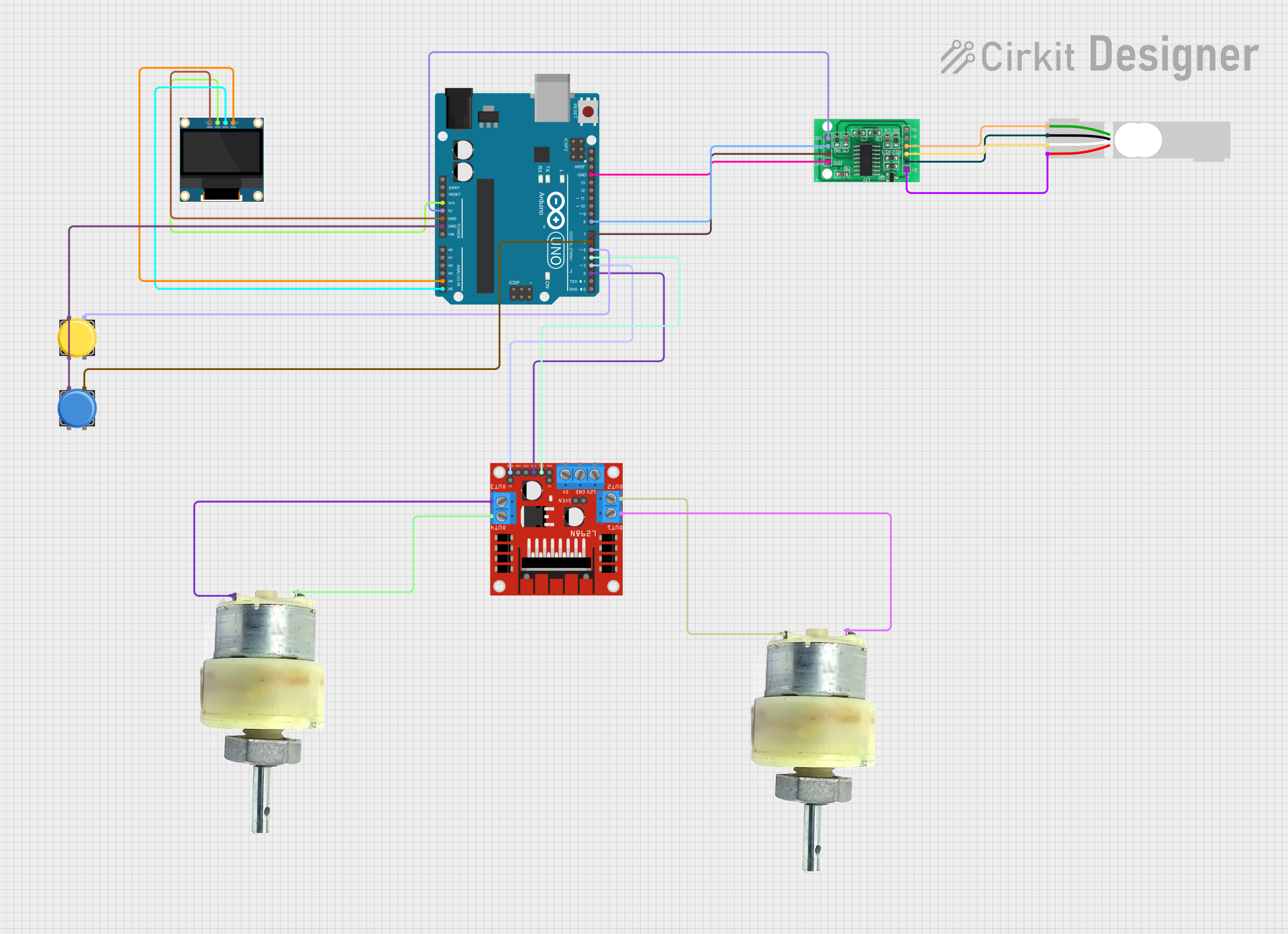
This circuit is designed to control a yarn tension adjustment system. It utilizes an Arduino UNO microcontroller to interface with various components including an OLED display, pushbuttons, a load cell with an HX711 interface, and a motor driver to control two 12V geared motors. The system reads the tension from the load cell, displays the set and actual tension values on the OLED display, and allows the user to adjust the set tension using pushbuttons.
Component List
Arduino UNO
- Description: Microcontroller board based on the ATmega328P.
- Pins: UNUSED, IOREF, Reset, 3.3V, 5V, GND, Vin, A0, A1, A2, A3, A4, A5, SCL, SDA, AREF, D13, D12, D11, D10, D9, D8, D7, D6, D5, D4, D3, D2, D1, D0
0.96" OLED
- Description: Small OLED display module.
- Pins: GND, VDD, SCK, SDA
Pushbutton
- Description: Simple pushbutton switch.
- Pins: Pin 2, Pin 1, Pin 3, Pin 4
Pushbutton
- Description: Simple pushbutton switch.
- Pins: Pin 2, Pin 1, Pin 3, Pin 4
HX711 - Bridge Sensor Interface
- Description: Load cell amplifier and ADC.
- Pins: E+, E-, A-, A+, B-, B+, GND - GROUND, DATA (OUT), SCK - CLOCK (IN), 3.3/3.5V Supply
Load Cell - Red/white/black/green
- Description: Load cell sensor for measuring weight or force.
- Pins: E+, A-, E-, A+
12V Geared Motor
- Description: DC motor with gear reduction.
- Pins: Terminal 1, Terminal 2
12V Geared Motor
- Description: DC motor with gear reduction.
- Pins: Terminal 1, Terminal 2
L298N DC Motor Driver
- Description: Dual H-Bridge motor driver.
- Pins: OUT1, OUT2, 12V, GND, 5V, OUT3, OUT4, 5V-ENA-JMP-I, 5V-ENA-JMP-O, +5V-J1, +5V-J2, ENA, IN1, IN2, IN3, IN4, ENB
Wiring Details
Arduino UNO
- 3.3V: Connected to VDD of 0.96" OLED
- 5V: Connected to 3.3/3.5V Supply of HX711 - Bridge Sensor Interface
- GND: Connected to GND of 0.96" OLED, GND - GROUND of HX711 - Bridge Sensor Interface, and Pin 1 of both Pushbuttons
- A4: Connected to SDA of 0.96" OLED
- A5: Connected to SCK of 0.96" OLED
- D8: Connected to SCK - CLOCK (IN) of HX711 - Bridge Sensor Interface
- D7: Connected to DATA (OUT) of HX711 - Bridge Sensor Interface
- D6: Connected to Pin 3 of Pushbutton
- D5: Connected to Pin 3 of Pushbutton
- D4: Connected to IN1 of L298N DC Motor Driver
- D3: Connected to ENB of L298N DC Motor Driver
- D2: Connected to IN2 of L298N DC Motor Driver
0.96" OLED
- GND: Connected to GND of Arduino UNO
- VDD: Connected to 3.3V of Arduino UNO
- SCK: Connected to A5 of Arduino UNO
- SDA: Connected to A4 of Arduino UNO
Pushbutton
- Pin 1: Connected to GND of Arduino UNO
- Pin 3: Connected to D6 of Arduino UNO
Pushbutton
- Pin 1: Connected to GND of Arduino UNO
- Pin 3: Connected to D5 of Arduino UNO
HX711 - Bridge Sensor Interface
- 3.3/3.5V Supply: Connected to 5V of Arduino UNO
- GND - GROUND: Connected to GND of Arduino UNO
- SCK - CLOCK (IN): Connected to D8 of Arduino UNO
- DATA (OUT): Connected to D7 of Arduino UNO
Load Cell - Red/white/black/green
- E+: Connected to E+ of HX711 - Bridge Sensor Interface
- E-: Connected to E- of HX711 - Bridge Sensor Interface
- A-: Connected to A- of HX711 - Bridge Sensor Interface
- A+: Connected to A+ of HX711 - Bridge Sensor Interface
12V Geared Motor
- Terminal 1: Connected to OUT1 of L298N DC Motor Driver
- Terminal 2: Connected to OUT2 of L298N DC Motor Driver
12V Geared Motor
- Terminal 1: Connected to OUT4 of L298N DC Motor Driver
- Terminal 2: Connected to OUT3 of L298N DC Motor Driver
L298N DC Motor Driver
- IN1: Connected to D4 of Arduino UNO
- ENB: Connected to D3 of Arduino UNO
- IN2: Connected to D2 of Arduino UNO
Code Documentation
#include <Arduino.h>
#include <Keypad.h>
#include <Wire.h>
#include <Adafruit_GFX.h>
#include <Adafruit_SSD1306.h>
#include "HX711.h"
#include "L298N_MotorDriver.h"

// OLED display
Adafruit_SSD1306 DIS = Adafruit_SSD1306(128, 64, &Wire);

// Motor driver
L298N_MotorDriver motor(3, 2, 4);

// Load cell
const int LOADCELL_DOUT_PIN = 8;
const int LOADCELL_SCK_PIN = 7;
HX711 scale;

// Button pins
int sw1 = 5;
int sw2 = 6;
int sw3 = 9;
int sw4 = 10;

// Variables
boolean run = 1;
int set = 50;
int actual = 502;
long sensee;
int scl;

// Button handling
const int increaseButtonPin = 5; // Pin for the increase button
const int decreaseButtonPin = 6; // Pin for the decrease button
int setValue = 400; // Variable to store the set value
int lastIncreaseState = HIGH; // Last state of the increase button
int lastDecreaseState = HIGH; // Last state of the decrease button

void setup() {
  // Pin modes
  pinMode(13, OUTPUT);
  pinMode(sw1, INPUT_PULLUP);
  pinMode(sw2, INPUT_PULLUP);
  pinMode(sw3, INPUT_PULLUP);
  pinMode(sw4, INPUT_PULLUP);

  // Serial communication
  Serial.begin(57600);

  // Initialize load cell
  scale.begin(LOADCELL_DOUT_PIN, LOADCELL_SCK_PIN);

  // Initialize OLED display
  DIS.begin(SSD1306_SWITCHCAPVCC, 0x3C);

  // Initialize motor driver
  motor.setDirection(true); // Sets the direction (depending on the wiring)
  motor.enable();
}

void diss() {
  DIS.clearDisplay();
  DIS.setTextColor(WHITE);
  DIS.setTextSize(1);
  DIS.setCursor(7, 0);
  DIS.print("YARN TENSION ADJST");

  DIS.setTextSize(2);
  DIS.setCursor(10, 22);
  DIS.print("SET");

  DIS.setTextSize(2);
  DIS.setCursor(10, 45);
  DIS.print("ACT");

  DIS.setCursor(70, 22);
  DIS.print(set);

  DIS.setCursor(70, 45);
  DIS.print(scl);

  DIS.display();
  DIS.dim(false);
}

void load() {
  if (scale.is_ready()) {
    long reading = scale.read();
    sensee = reading / 100.0;
    scl = map(sensee, 2853, 3300, 0, 1000);
  } else {
    Serial.println("HX711 not found.");
  }
}

void loop()