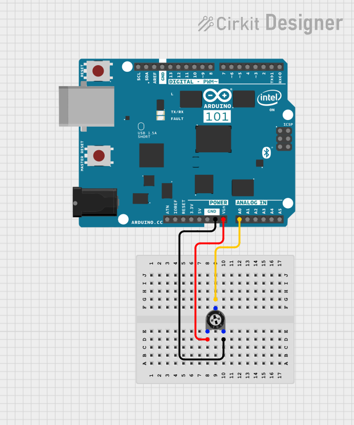
Arduino 101 Analog Input Control with Trimmer Potentiometer

Circuit Documentation
Summary of the Circuit
This circuit consists of an Arduino 101 microcontroller board interfaced with a trimmer potentiometer. The potentiometer is connected to the Arduino to provide an adjustable voltage input that can be read by one of the Arduino's analog input pins. The purpose of this setup is likely to allow for the measurement of the potentiometer's position, which can be used to control variables in a program running on the Arduino, such as the brightness of an LED, motor speed, or other analog control applications.
Component List
Arduino 101
- Description: A microcontroller board based on the Intel Curie Module, designed for building IoT applications. It has a rich set of features including Bluetooth Low Energy (BLE) capabilities and a built-in 6-axis accelerometer/gyroscope.
- Pins: A5/SCL, A4/SDA, AREF, GND, D13/SCK, D12/MISO, D11 PWM/MOSI, D10 PWM/SS, D9 PWM, D8, D7, D6 PWM, D5 PWM, D4, D3 PWM, D2, D1/TX, D0/RX, AIN, ioref, RESET, 3V3, 5V, VIN, A0, A1, A2, A3, ICSP MISO, ICSP SCK, ICSP MOSI.
Trimmer Potentiometer
- Description: A three-terminal resistor with a continuously adjustable tapping point controlled by rotation of a shaft or knob.
- Pins: leg1, wiper, leg2.
- Properties: Resistance - 10,000 Ohms.
Wiring Details
Arduino 101
- VIN: Connected to leg1 of the Trimmer Potentiometer.
- A0: Connected to the wiper of the Trimmer Potentiometer.
- GND: Connected to leg2 of the Trimmer Potentiometer.
Trimmer Potentiometer
- leg1: Connected to VIN of the Arduino 101.
- wiper: Connected to A0 of the Arduino 101.
- leg2: Connected to GND of the Arduino 101.
Documented Code
There is no code provided for the microcontroller in this circuit. If code were provided, it would typically be used to read the analog voltage from pin A0, which corresponds to the position of the potentiometer's wiper, and then perform some action based on this value. Since no code is available, it is recommended to write a simple Arduino sketch that initializes the serial communication and reads the analog value from pin A0 in a loop, printing this value to the serial monitor.