Cirkit Designer
Your all-in-one circuit design IDE
Home /
Project Documentation
Arduino UNO Controlled Security System with RFID, Alcohol Sensor, and Relay-Operated Magnetic Lock

Circuit Documentation
Summary
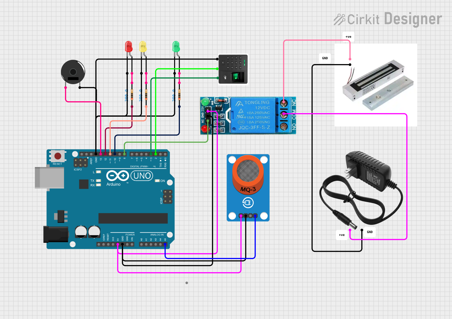
The circuit in question appears to be a microcontroller-based system designed to interface with various sensors, actuators, and indicators. The core of the system is an Arduino UNO, which controls LEDs, a piezo buzzer, a relay for a magnetic lock, and interfaces with an MQ-3 alcohol sensor and an RFID card reader. The circuit is powered by a 12V power supply, and the Arduino UNO regulates the voltage for its peripherals. The LEDs are current-limited by resistors, and the relay controls the magnetic lock based on the logic from the Arduino.
Component List
LEDs
- Red LED: A two-pin red LED used as an indicator.
- Yellow LED: A two-pin yellow LED used as an indicator.
- Green LED: A two-pin green LED used as an indicator.
Resistors
- 200 Ohm Resistors: Three resistors each with a resistance of 200 Ohms, used to limit current to the LEDs.
Microcontroller
- Arduino UNO: A microcontroller board based on the ATmega328P, with digital and analog I/O pins.
Piezo Buzzer
- Piezo Buzzer: An electronic device that emits a tone when voltage is applied.
RFID Card Reader
- RFID Card Reader with Wiegand Output: A device that reads RFID cards and outputs data in Wiegand format.
Alcohol Sensor
- MQ-3 Alcohol Sensor: A gas sensor used for detecting alcohol levels in the air.
Magnetic Lock
- Magnetic Lock: An electromagnetic lock for security purposes.
Power Supply
- 12V Power Supply: Provides power to the circuit.
Relay
- 12V Single Channel Relay: An electromechanical switch used for controlling high power devices.
Wiring Details
Red LED
- Cathode connected to GND.
- Anode connected to a 200 Ohm resistor.
Yellow LED
- Cathode connected to GND.
- Anode connected to a 200 Ohm resistor.
Green LED
- Cathode connected to GND.
- Anode connected to a 200 Ohm resistor.
200 Ohm Resistors
- One side connected to the anode of each LED.
- Other side connected to the corresponding digital pins on the Arduino UNO (D12, D11, D10).
Arduino UNO
- 5V and GND pins provide power to the relay and MQ-3 sensor.
- A5 pin reads analog output from the MQ-3 sensor.
- D13 pin controls the piezo buzzer.
- D8 pin controls the relay input.
- D3 and D2 pins interface with the RFID reader's Wiegand outputs.
Piezo Buzzer
- One pin connected to D13 on the Arduino UNO.
- Other pin connected to GND.
RFID Card Reader
- GND pin connected to GND.
- Wiegand output pins connected to D3 and D2 on the Arduino UNO.
MQ-3 Alcohol Sensor
- VCC pin connected to 5V.
- GND pin connected to GND.
- AO pin connected to A5 on the Arduino UNO.
Magnetic Lock
- S pin connected to the Normally Closed (NC) terminal of the relay.
- GND pin connected to the negative terminal of the power supply.
12V Power Supply
- Positive terminal connected to the Common (COM) terminal of the relay.
- Negative terminal provides GND for the magnetic lock.
Relay
- VCC pin connected to 5V.
- GND pin connected to GND.
- IN pin controlled by D8 on the Arduino UNO.
- NC terminal connected to the magnetic lock.
- COM terminal connected to the positive terminal of the power supply.
Documented Code
Arduino UNO Code (sketch.ino)
void setup() {
  // put your setup code here, to run once:

}

void loop() {
  // put your main code here, to run repeatedly:

}
Additional Notes (documentation.txt)
No additional code documentation provided.