
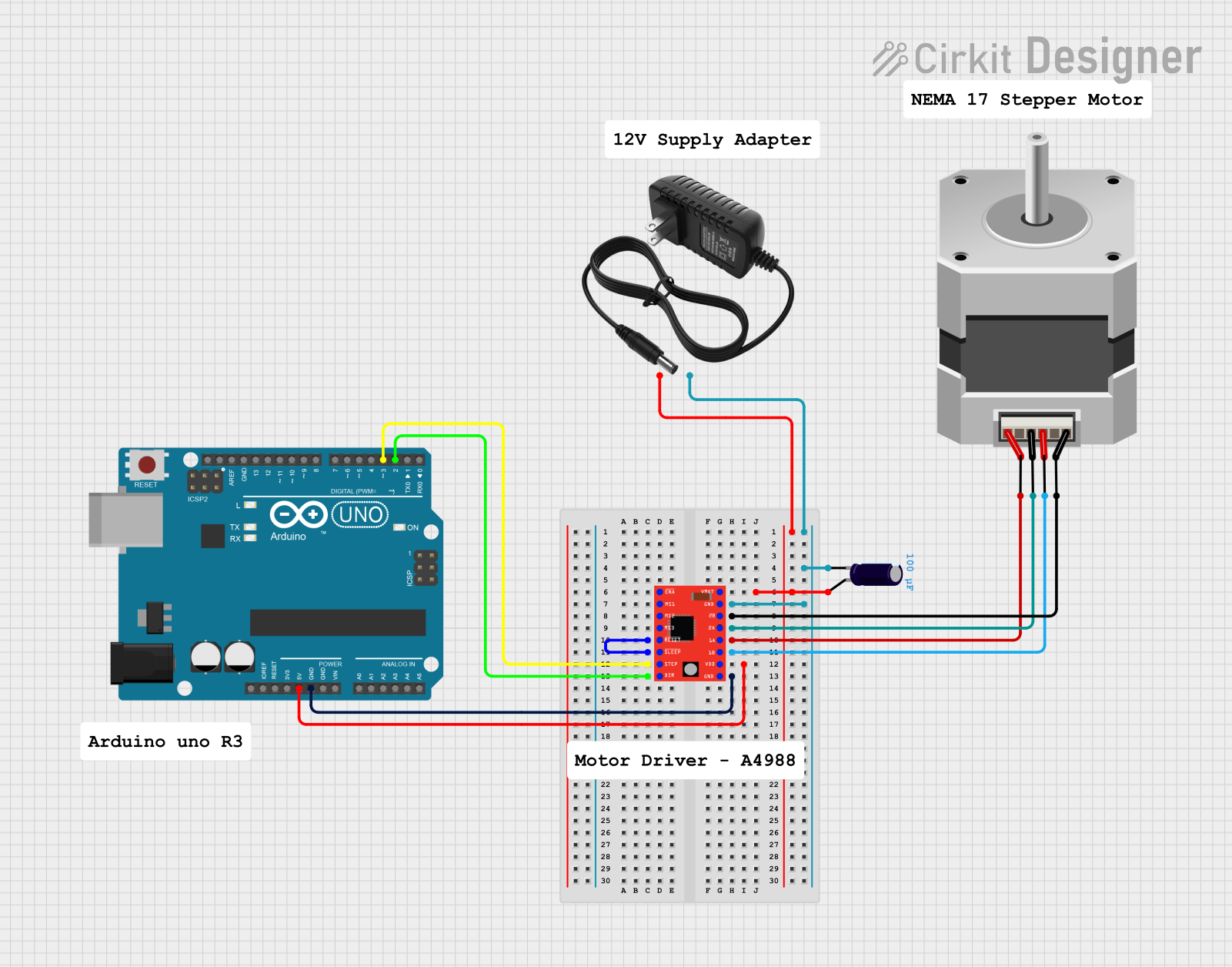
Circuit Documentation
Summary
This circuit is designed to control a bipolar stepper motor using an Arduino UNO microcontroller and an A4988 stepper motor driver. The A4988 driver allows for precise control of the motor steps and direction, while the Arduino UNO provides the logic and timing for the stepping sequence. A 12V power supply is used to power the motor through the A4988 driver, and an electrolytic capacitor is included to stabilize the voltage supply to the motor driver.
Component List
Arduino UNO
- Microcontroller board based on the ATmega328P
- Provides the control logic for the stepper motor driver
- Pins used: IOREF, Reset, 3.3V, 5V, GND, Vin, A0-A5, SCL, SDA, AREF, D0-D13
Stepper Motor (Bipolar)
- A four-wire bipolar stepper motor
- Controlled by the A4988 stepper motor driver
- Pins used: A, B, C, D
A4988 Stepper Motor Driver (Red)
- A compact driver for controlling stepper motors
- Interfaces between the Arduino UNO and the bipolar stepper motor
- Pins used: ENABLE, MS1-MS3, RESET, SLEEP, STEP, DIR, VMOT, GND, 1A, 1B, 2A, 2B, VDD
12V Power Supply
- Provides the necessary voltage and current to drive the stepper motor
- Pins used: + (positive voltage), - (ground)
Electrolytic Capacitor
- Used to filter and stabilize the voltage supply to the A4988 driver
- Capacitance: 0.0001 Farads
- Pins used: + (positive), - (negative)
Wiring Details
Arduino UNO
- D2 connected to A4988 DIR pin (Direction control)
- D3 connected to A4988 STEP pin (Step control)
- 5V connected to A4988 VDD pin (Logic voltage supply)
- GND connected to A4988 GND pin (Ground)
Stepper Motor (Bipolar)
- A connected to A4988 1A pin
- B connected to A4988 1B pin
- C connected to A4988 2A pin
- D connected to A4988 2B pin
A4988 Stepper Motor Driver (Red)
- VMOT connected to 12V power supply positive and Electrolytic Capacitor positive
- GND connected to 12V power supply negative and Electrolytic Capacitor negative
- SLEEP connected to RESET (Enables the driver and resets any internal logic)
- STEP connected to Arduino UNO D3 (Step control)
- DIR connected to Arduino UNO D2 (Direction control)
- VDD connected to Arduino UNO 5V (Logic voltage supply)
- GND connected to Arduino UNO GND (Ground)
12V Power Supply
-
- connected to A4988 VMOT pin and Electrolytic Capacitor positive
-
- connected to A4988 GND pin and Electrolytic Capacitor negative
Electrolytic Capacitor
-
- connected to A4988 VMOT pin and 12V power supply positive
-
- connected to A4988 GND pin and 12V power supply negative
Documented Code
Arduino UNO - sketch.ino
void setup() {
  // put your setup code here, to run once:

}

void loop() {
  // put your main code here, to run repeatedly:

}
Arduino UNO - documentation.txt
(No additional documentation provided)
This concludes the documentation for the stepper motor control circuit. The circuit is designed for modularity and can be expanded or modified for various applications involving stepper motor control.