
Arduino Mega 2560 Controlled Traffic Light System with TM1637 Displays
View and Edit Project In Cirkit Designer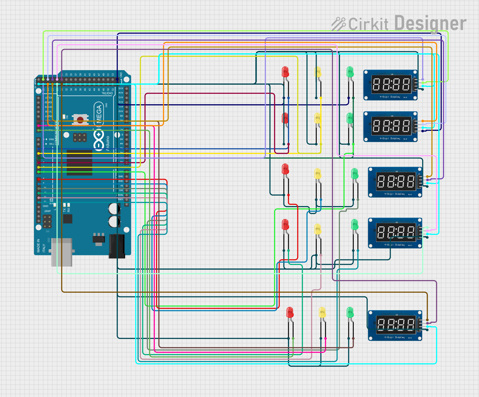
Circuit Documentation
Summary
This circuit is designed to control a series of traffic signal lights, represented by red, yellow, and green LEDs, and display countdown timers on TM1637 4-digit 7-segment displays. The control logic for the LEDs and the displays is managed by an Arduino Mega 2560 microcontroller, which drives the LEDs directly through its PWM-capable digital I/O pins and communicates with the TM1637 displays via I2C protocol.
Component List
LEDs
- Red LEDs: Two-pin LEDs that emit red light.
- Yellow LEDs: Two-pin LEDs that emit yellow light.
- Green LEDs: Two-pin LEDs that emit green light.
TM1637 Displays
- TM1637: A module with a 4-digit 7-segment display that is controlled via a 2-wire interface (CLK and DIO).
Microcontroller
- Arduino Mega 2560: A microcontroller board based on the ATmega2560 with numerous digital and analog I/O pins.
Wiring Details
Red LEDs
- Anode: Connected to the Arduino Mega 2560's PWM-capable digital pins (D2, D5, D8, D11, D14).
- Cathode: Connected to the common ground.
Yellow LEDs
- Anode: Connected to the Arduino Mega 2560's PWM-capable digital pins (D3, D6, D9, D12, D15).
- Cathode: Connected to the common ground.
Green LEDs
- Anode: Connected to the Arduino Mega 2560's PWM-capable digital pins (D4, D7, D10, D13, D16).
- Cathode: Connected to the common ground.
TM1637 Displays
- CLK: Connected to the Arduino Mega 2560's digital pins (D22, D24, D26, D28, D30).
- DIO: Connected to the Arduino Mega 2560's digital pins (D23, D25, D27, D29, D31).
- VCC: Connected to the Arduino Mega 2560's 5V power supply.
- GND: Connected to the common ground.
Arduino Mega 2560
- PWM Pins: Used to drive the anodes of the LEDs.
- Digital I/O Pins: Used to communicate with the TM1637 displays.
- 5V and GND: Provide power to the TM1637 displays and serve as the common ground for the LEDs.
Documented Code
#include <Wire.h>
#include <Adafruit_GFX.h>
#include <Adafruit_LEDBackpack.h>

#define NUM_SIGNALS 5

// Define pin numbers for each LED on each signal
const int redPins[NUM_SIGNALS] = {2, 5, 8, 11, 14};
const int yellowPins[NUM_SIGNALS] = {3, 6, 9, 12, 15};
const int greenPins[NUM_SIGNALS] = {4, 7, 10, 13, 16};

// Create 5 instances for 5 traffic lights
Adafruit_7segment display[NUM_SIGNALS] = {
    Adafruit_7segment(), Adafruit_7segment(), Adafruit_7segment(), Adafruit_7segment(), Adafruit_7segment()
};

// Define the I2C addresses for each display
const uint8_t i2cAddress[NUM_SIGNALS] = { 0x70, 0x71, 0x72, 0x73, 0x74 };

enum LightState {RED, YELLOW_TO_GREEN, GREEN, YELLOW_TO_RED};

struct TrafficLight {
    LightState state;
    int counter;
};

TrafficLight signals[NUM_SIGNALS];

void setup() {
    // Initialize each traffic signal's LED pins and display
    for (int i = 0; i < NUM_SIGNALS; i++) {
        display[i].begin(i2cAddress[i]);
        signals[i].state = RED;
        signals[i].counter = 10;  // Start with RED countdown
        display[i].print(signals[i].counter);
        display[i].writeDisplay();

        // Initialize LED pins as outputs
        pinMode(redPins[i], OUTPUT);
        pinMode(yellowPins[i], OUTPUT);
        pinMode(greenPins[i], OUTPUT);

        // Set initial LED states (RED ON, others OFF)
        digitalWrite(redPins[i], HIGH);
        digitalWrite(yellowPins[i], LOW);
        digitalWrite(greenPins[i], LOW);
    }
}

void loop() {
    for (int i = 0; i < NUM_SIGNALS; i++) {
        updateSignal(i);
    }
    delay(1000);  // 1-second delay for countdown
}

void updateSignal(int signal) {
    switch (signals[signal].state) {
        case RED:
            digitalWrite(redPins[signal], HIGH);
            digitalWrite(yellowPins[signal], LOW);
            digitalWrite(greenPins[signal], LOW);
            signals[signal].counter--;
            if (signals[signal].counter == 0) {
                signals[signal].state = YELLOW_TO_GREEN;
                signals[signal].counter = 3;
            }
            break;
        case YELLOW_TO_GREEN:
            digitalWrite(redPins[signal], LOW);
            digitalWrite(yellowPins[signal], HIGH);
            digitalWrite(greenPins[signal], LOW);
            signals[signal].counter--;
            if (signals[signal].counter == 0) {
                signals[signal].state = GREEN;
                signals[signal].counter = 5;
            }
            break;
        case GREEN:
            digitalWrite(redPins[signal], LOW);
            digitalWrite(yellowPins[signal], LOW);
            digitalWrite(greenPins[signal], HIGH);
            signals[signal].counter--;
            if (signals[signal].counter == 0) {
                signals[signal].state = YELLOW_TO_RED;
                signals[signal].counter = 3;
            }
            break;
        case YELLOW_TO_RED:
            digitalWrite(redPins[signal], LOW);
            digitalWrite(yellowPins[signal], HIGH);
            digitalWrite(greenPins[signal], LOW);
            signals[signal].counter--;
            if (signals[signal].counter == 0) {
                signals[signal].state = RED;
                signals[signal].counter = 10;
            }
            break;
    }

    // Update the display with the current countdown
    display[signal].print(signals[signal].counter);
    display[signal].writeDisplay();
}
This code is responsible for controlling the state and timing of each traffic light signal. It uses an array of Adafruit_7segment objects to manage the displays and an array of TrafficLight structs to keep track of the state and countdown for each signal. The setup() function initializes the displays and sets the initial state of each traffic light to RED with a countdown of 10 seconds. The loop() function continuously updates each signal based on its current state and countdown timer. The updateSignal() function handles the state transitions and updates the corresponding LED and display for each traffic light.