
Arduino-Controlled Bluetooth Robotic Vehicle with LED Indicators
View and Edit Project In Cirkit Designer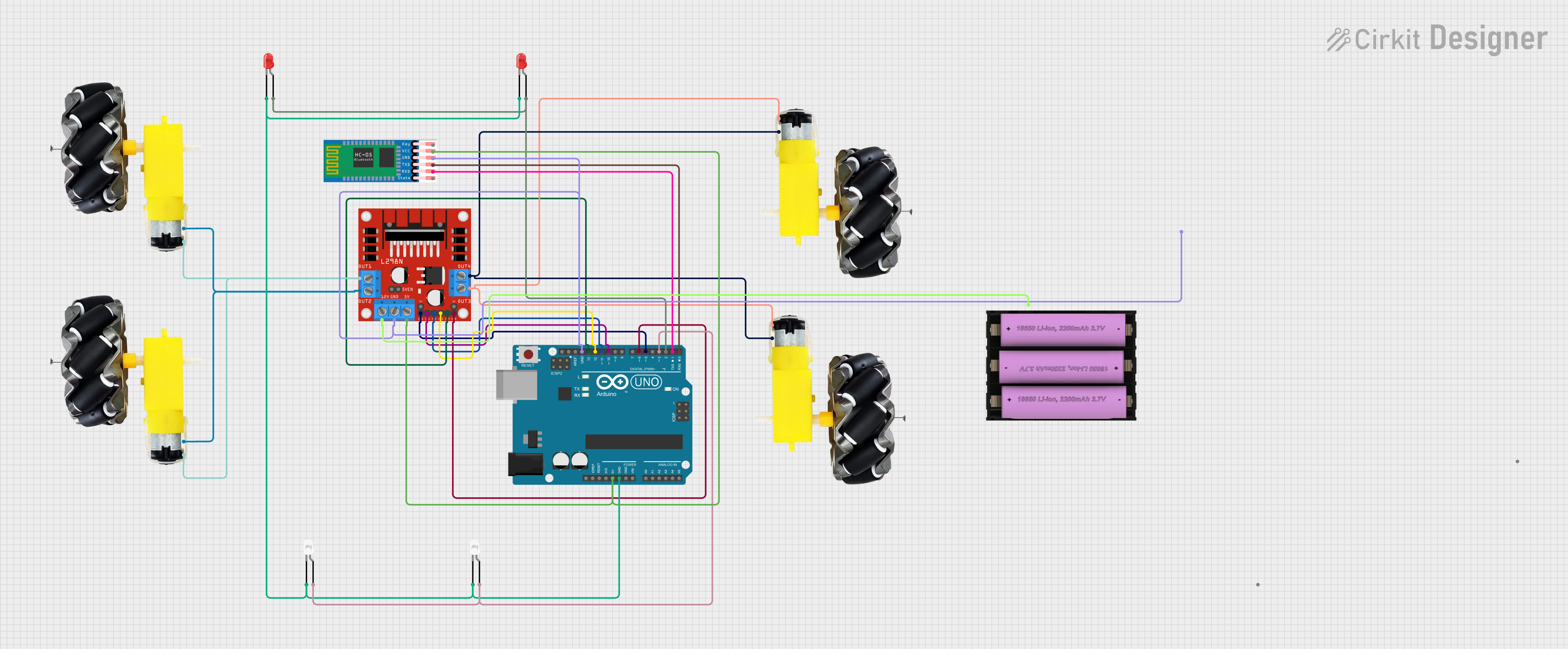
Circuit Documentation
Summary
This circuit is designed to control a set of motors using an Arduino UNO microcontroller and an L298N DC motor driver. It includes a Bluetooth module (HC-05) for wireless communication and LEDs for status indication. The power is supplied by a 7V battery. The Arduino UNO is programmed to interface with the motor driver and the Bluetooth module to control the motors based on the received commands.
Component List
Arduino UNO
- Microcontroller board based on the ATmega328P
- It has 14 digital input/output pins, 6 analog inputs, a 16 MHz quartz crystal, a USB connection, a power jack, an ICSP header, and a reset button.
L298N DC Motor Driver
- A dual H-bridge motor driver capable of driving a pair of DC motors or a stepper motor.
- It has 2 input power pins, 4 input control pins, and 4 output pins to the motors.
Motors and Wheels (4x)
- DC motors connected to wheels, used for the motion of a vehicle or robot.
- Each motor has a VCC and GND pin for power connection.
LEDs (4x)
- Two red and two white LEDs used for status indication.
- Each LED has an anode and cathode pin.
HC-05 Bluetooth Module
- A wireless communication module that can be used to exchange data with other Bluetooth devices.
- It has pins for enabling, power supply, ground, and serial communication (TXD, RXD).
Set Battery (7V)
- A power source for the circuit.
- It has a positive (+) and negative (-) terminal.
Wiring Details
Arduino UNO
- 5V pin connected to the 5V pin of the L298N motor driver and VCC of HC-05.
- GND pin connected to the cathodes of all LEDs, GND of L298N, and GND of HC-05.
- Digital pins D2 and D3 connected to the anodes of the red and white LEDs, respectively.
- Digital pins D5 and D6 connected to ENA and ENB of the L298N to enable motor channels.
- Digital pins D10 to D13 connected to IN1 to IN4 of the L298N for motor control.
- Digital pins D0 and D1 connected to TXD and RXD of HC-05 for serial communication.
L298N DC Motor Driver
- 5V pin connected to the 5V pin of Arduino UNO and VCC of HC-05.
- GND pin connected to the GND of Arduino UNO and negative terminal of the battery.
- IN1 to IN4 pins connected to D10 to D13 of Arduino UNO for motor control.
- ENA and ENB pins connected to D5 and D6 of Arduino UNO to enable motor channels.
- OUT1 and OUT2 connected to the motors associated with the first channel.
- OUT3 and OUT4 connected to the motors associated with the second channel.
- 12V pin connected to the positive terminal of the battery.
Motors and Wheels
- VCC of each motor connected to OUT1/OUT3 of the L298N.
- GND of each motor connected to OUT2/OUT4 of the L298N.
LEDs
- Anodes of the red LEDs connected to D2 of Arduino UNO.
- Anodes of the white LEDs connected to D3 of Arduino UNO.
- Cathodes of all LEDs connected to GND of Arduino UNO.
HC-05 Bluetooth Module
- VCC connected to the 5V pin of Arduino UNO.
- GND connected to the GND pin of Arduino UNO.
- TXD connected to D0 of Arduino UNO.
- RXD connected to D1 of Arduino UNO.
Set Battery (7V)
- Positive terminal connected to the 12V pin of the L298N.
- Negative terminal connected to the GND pin of the L298N.
Documented Code
Arduino UNO Code (sketch.ino)
void setup() {
  // put your setup code here, to run once:

}

void loop() {
  // put your main code here, to run repeatedly:

}
Note: The provided code is a template and does not contain any functional code to control the motors or communicate with the HC-05 Bluetooth module. The user is expected to write the necessary code to implement the desired functionality.