Cirkit Designer
Your all-in-one circuit design IDE
Home /
Project Documentation
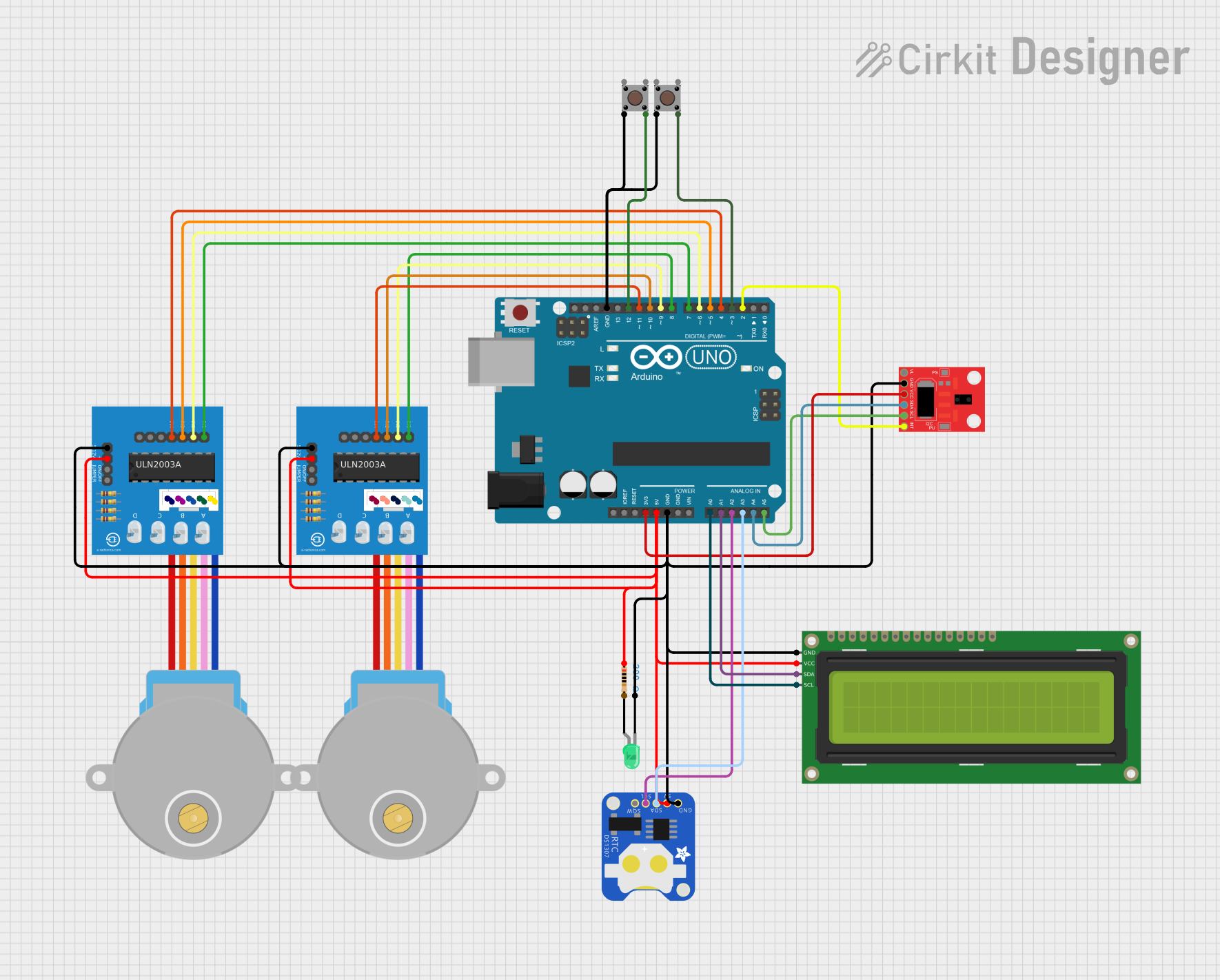
Arduino UNO-Based Dual Stepper Motor Controller with Gesture Sensing and RTC Display
Circuit Documentation
Summary
This project is an Arduino UNO-based dual stepper motor controller with gesture sensing and RTC display. The circuit includes the following components:
- Arduino UNO
- Two 28BYJ-48 Stepper Motors with ULN2003A Driver Boards
- APDS-9960 RGB and Gesture Sensor
- DS1307 RTC Module
- 16x2 I2C LCD Display
- Green LED with Resistor
- Two Pushbuttons
The functionality of the circuit includes controlling two stepper motors using ULN2003A driver boards, displaying RTC time on a 16x2 I2C LCD, using the APDS-9960 for gesture-based control, indicating status with a green LED, and using pushbuttons for additional control.
Component List
Arduino UNO
- Description: Microcontroller board based on the ATmega328P.
- Pins: UNUSED, IOREF, Reset, 3.3V, 5V, GND, Vin, A0, A1, A2, A3, A4, A5, SCL, SDA, AREF, D13, D12, D11, D10, D9, D8, D7, D6, D5, D4, D3, D2, D1, D0
28BYJ-48 Stepper Motor
- Description: 5V stepper motor.
- Pins: BLUE, PINK, YELLOW, ORANGE, RED
ULN2003A Breakout Board
- Description: Driver board for stepper motors.
- Pins: In 1, In 2, In 3, In 4, In 5, In 6, In 7, 0V, +5V, ON/OFF jumper switch, BLUE wire, PINK wire, YELLOW wire, ORANGE wire, RED wire
APDS-9960 RGB and Gesture Sensor
- Description: Sensor for RGB color and gesture detection.
- Pins: VL, GND, VCC, SDA, SCL, INT
DS1307 RTC (Wokwi Compatible)
- Description: Real-time clock module.
- Pins: GND, 5V, SDA, SCL, SQW
LED: Two Pin (green)
- Description: Green LED.
- Pins: cathode, anode
Resistor
- Description: 200 Ohms resistor.
- Pins: pin1, pin2
Pushbutton
- Description: Pushbutton switch.
- Pins: Pin 3 (out), Pin 4 (out), Pin 1 (in), Pin 2 (in)
16x2 I2C LCD
- Description: 16x2 character LCD with I2C interface.
- Pins: GND, VCC, SDA, SCL
Wiring Details
Arduino UNO
- 3.3V to VCC of APDS-9960 RGB and Gesture Sensor
- 5V to pin1 of Resistor, +5V of both ULN2003A Breakout Boards, VCC of 16x2 I2C LCD, 5V of DS1307 RTC
- GND to 0V of both ULN2003A Breakout Boards, cathode of LED, GND of APDS-9960 RGB and Gesture Sensor, GND of 16x2 I2C LCD, GND of DS1307 RTC, Pin 2 (in) of both Pushbuttons
- A0 to SCL of 16x2 I2C LCD
- A1 to SDA of 16x2 I2C LCD
- A2 to SCL of DS1307 RTC
- A3 to SDA of DS1307 RTC
- A4 to SDA of APDS-9960 RGB and Gesture Sensor
- A5 to SCL of APDS-9960 RGB and Gesture Sensor
- D2 to INT of APDS-9960 RGB and Gesture Sensor
- D3 to Pin 4 (out) of Pushbutton
- D4 to In 4 of ULN2003A Breakout Board (second)
- D5 to In 3 of ULN2003A Breakout Board (second)
- D6 to In 2 of ULN2003A Breakout Board (second)
- D7 to In 1 of ULN2003A Breakout Board (second)
- D8 to In 1 of ULN2003A Breakout Board (first)
- D9 to In 2 of ULN2003A Breakout Board (first)
- D10 to In 3 of ULN2003A Breakout Board (first)
- D11 to In 4 of ULN2003A Breakout Board (first)
- D12 to Pin 4 (out) of Pushbutton
28BYJ-48 Stepper Motor (first)
- BLUE to BLUE wire of ULN2003A Breakout Board (first)
- PINK to PINK wire of ULN2003A Breakout Board (first)
- YELLOW to YELLOW wire of ULN2003A Breakout Board (first)
- ORANGE to ORANGE wire of ULN2003A Breakout Board (first)
- RED to RED wire of ULN2003A Breakout Board (first)
28BYJ-48 Stepper Motor (second)
- BLUE to BLUE wire of ULN2003A Breakout Board (second)
- PINK to PINK wire of ULN2003A Breakout Board (second)
- YELLOW to YELLOW wire of ULN2003A Breakout Board (second)
- ORANGE to ORANGE wire of ULN2003A Breakout Board (second)
- RED to RED wire of ULN2003A Breakout Board (second)
APDS-9960 RGB and Gesture Sensor
- VCC to 3.3V of Arduino UNO
- GND to GND of Arduino UNO
- SDA to A4 of Arduino UNO
- SCL to A5 of Arduino UNO
- INT to D2 of Arduino UNO
DS1307 RTC (Wokwi Compatible)
- GND to GND of Arduino UNO
- 5V to 5V of Arduino UNO
- SDA to A3 of Arduino UNO
- SCL to A2 of Arduino UNO
LED: Two Pin (green)
- cathode to GND of Arduino UNO
- anode to pin2 of Resistor
Resistor
- pin1 to 5V of Arduino UNO
- pin2 to anode of LED
Pushbutton (first)
- Pin 2 (in) to GND of Arduino UNO
- Pin 4 (out) to D12 of Arduino UNO
Pushbutton (second)
- Pin 2 (in) to GND of Arduino UNO
- Pin 4 (out) to D3 of Arduino UNO
16x2 I2C LCD
- GND to GND of Arduino UNO
- VCC to 5V of Arduino UNO
- SDA to A1 of Arduino UNO
- SCL to A0 of Arduino UNO
Code Documentation
/*
 * Arduino UNO-Based Dual Stepper Motor Controller with Gesture Sensing and RTC Display
 *
 * Components:
 * - Arduino UNO
 * - Two 28BYJ-48 Stepper Motors with ULN2003A Driver Boards
 * - APDS-9960 RGB and Gesture Sensor
 * - DS1307 RTC Module
 * - 16x2 I2C LCD Display
 * - Green LED with Resistor
 * - Two Pushbuttons
 *
 * Functionality:
 * - Control two stepper motors using ULN2003A driver boards
 * - Display RTC time on 16x2 I2C LCD
 * - Use APDS-9960 for gesture-based control
 * - Indicate status with a green LED
 * - Use pushbuttons for additional control
 */

#include <Wire.h>
#include <LiquidCrystal_I2C.h>
#include <Stepper.h>
#include <Adafruit_APDS9960.h>
#include <RTClib.h>

// Pin definitions
#define LED_PIN A1
#define BUTTON1_PIN 3
#define BUTTON2_PIN 12

// Stepper motor pins
#define STEPPER1_IN1 7
#define STEPPER1_IN2 6
#define STEPPER1_IN3 5