
Arduino UNO-Based Smart Gas Detection and Monitoring System with LCD Display and Servo Control
View and Edit Project In Cirkit Designer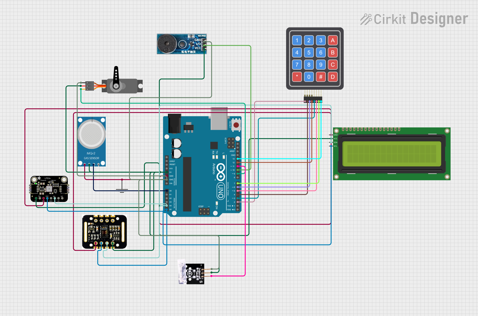
Circuit Documentation
Summary
This circuit is designed to interface an Arduino UNO with various sensors and modules, including an MQ-2 gas sensor, a 16x2 I2C LCD, a servo motor, a MAX30102 HR + SpO2 sensor, an Adafruit LPS35HW sensor, a 4x4 Keypad, a buzzer module, and a tap switch. The Arduino UNO reads data from the sensors, displays information on the LCD, and controls the servo and buzzer based on sensor inputs.
Component List
Arduino UNO
- Description: Microcontroller board based on the ATmega328P.
- Pins: UNUSED, IOREF, Reset, 3.3V, 5V, GND, Vin, A0, A1, A2, A3, A4, A5, SCL, SDA, AREF, D13, D12, D11, D10, D9, D8, D7, D6, D5, D4, D3, D2, D1, D0
MQ-2
- Description: Gas sensor for detecting LPG, i-butane, propane, methane, alcohol, hydrogen, and smoke.
- Pins: GND, VCC, ANALOG, Digital
16x2 I2C LCD
- Description: 16x2 character LCD display with I2C interface.
- Pins: GND, VCC, SDA, SCL
Servo
- Description: Servo motor for precise control of angular position.
- Pins: GND, VCC, PWM
MAX30102 HR + SpO2 sensor
- Description: Heart rate and SpO2 sensor.
- Pins: INT, IRD, RD, GND, SCL, SDA, VIN
Adafruit LPS35HW
- Description: Pressure sensor.
- Pins: VCC, 3.3V, GND, SCK/SCL, SDO/ADR, SDI/SDA, CS, INT
4x4 Keypad (Simulator)
- Description: 4x4 matrix keypad.
- Pins: R1, C4, R2, C2, R3, R4, C1, C3
Buzzer Module
- Description: Buzzer for sound output.
- Pins: GND, Vcc, I/O
Tap Switch
- Description: Tap switch for detecting touch.
- Pins: GND, VCC, OUTPUT
GND
- Description: Ground connection.
- Pins: GND
Wiring Details
Arduino UNO
- 5V: Connected to VCC of Servo, 16x2 I2C LCD, MAX30102 HR + SpO2 sensor, Buzzer Module, Adafruit LPS35HW, Tap Switch, and MQ-2.
- GND: Connected to GND of 16x2 I2C LCD, MAX30102 HR + SpO2 sensor, Adafruit LPS35HW, MQ-2, Servo, Buzzer Module, Tap Switch, and GND.
- A0: Connected to ANALOG of MQ-2.
- A4: Connected to SDA of 16x2 I2C LCD, MAX30102 HR + SpO2 sensor, and Adafruit LPS35HW.
- A5: Connected to SCL of 16x2 I2C LCD, MAX30102 HR + SpO2 sensor, and Adafruit LPS35HW.
- D13: Connected to C4 of 4x4 Keypad.
- D12: Connected to R4 of 4x4 Keypad.
- D11: Connected to OUTPUT of Tap Switch.
- D10: Connected to I/O of Buzzer Module.
- D9: Connected to PWM of Servo.
- D7: Connected to C3 of 4x4 Keypad.
- D6: Connected to R3 of 4x4 Keypad.
- D5: Connected to C2 of 4x4 Keypad.
- D4: Connected to R2 of 4x4 Keypad.
- D3: Connected to C1 of 4x4 Keypad.
- D2: Connected to R1 of 4x4 Keypad.
MQ-2
- VCC: Connected to 5V of Arduino UNO.
- GND: Connected to GND of Arduino UNO.
- ANALOG: Connected to A0 of Arduino UNO.
16x2 I2C LCD
- VCC: Connected to 5V of Arduino UNO.
- GND: Connected to GND of Arduino UNO.
- SDA: Connected to A4 of Arduino UNO.
- SCL: Connected to A5 of Arduino UNO.
Servo
- VCC: Connected to 5V of Arduino UNO.
- GND: Connected to GND of Arduino UNO.
- PWM: Connected to D9 of Arduino UNO.
MAX30102 HR + SpO2 sensor
- VIN: Connected to 5V of Arduino UNO.
- GND: Connected to GND of Arduino UNO.
- SDA: Connected to A4 of Arduino UNO.
- SCL: Connected to A5 of Arduino UNO.
Adafruit LPS35HW
- VCC: Connected to 5V of Arduino UNO.
- GND: Connected to GND of Arduino UNO.
- SDI/SDA: Connected to A4 of Arduino UNO.
- SCK/SCL: Connected to A5 of Arduino UNO.
4x4 Keypad (Simulator)
- C4: Connected to D13 of Arduino UNO.
- R4: Connected to D12 of Arduino UNO.
- C3: Connected to D7 of Arduino UNO.
- R3: Connected to D6 of Arduino UNO.
- C2: Connected to D5 of Arduino UNO.
- R2: Connected to D4 of Arduino UNO.
- C1: Connected to D3 of Arduino UNO.
- R1: Connected to D2 of Arduino UNO.
Buzzer Module
- Vcc: Connected to 5V of Arduino UNO.
- GND: Connected to GND of Arduino UNO.
- I/O: Connected to D10 of Arduino UNO.
Tap Switch
- VCC: Connected to 5V of Arduino UNO.
- GND: Connected to GND of Arduino UNO.
- OUTPUT: Connected to D11 of Arduino UNO.
GND
- GND: Connected to GND of Arduino UNO.
Code Documentation
#include <Wire.h>
#include <LiquidCrystal_I2C.h>
#include <Servo.h>

// Initialize LCD
LiquidCrystal_I2C lcd(0x27, 16, 2);

// Initialize Servo
Servo myServo;

void setup() {
  // Initialize LCD
  lcd.begin();
  lcd.backlight();

  // Initialize Servo
  myServo.attach(9);

  // Initialize other sensors and modules
  pinMode(A0, INPUT); // MQ-2
  pinMode(10, OUTPUT); // Buzzer
  pinMode(11, INPUT); // Tap Switch

  // Setup code for other sensors (MAX30102, LPS35HW, etc.)
}

void loop() {
  // Read sensors
  int gasValue = analogRead(A0);
  int tapSwitchState = digitalRead(11);

  // Display values on LCD
  lcd.setCursor(0, 0);
  lcd.print("Gas: ");
  lcd.print(gasValue);

  // Control Servo based on sensor values
  if (gasValue > threshold) {
    myServo.write(90); // Adjust angle as needed
  } else {
    myServo.write(0);
  }

  // Sound buzzer if needed
  if (tapSwitchState == HIGH) {
    digitalWrite(10, HIGH);
  } else {
    digitalWrite(10, LOW);
  }

  // Add code for other sensors and functionalities
}
This code initializes the LCD, servo, and other sensors. It reads the gas value from the MQ-2 sensor and the state of the tap switch. The gas value is displayed on the LCD, and the servo is controlled based on the gas value. The buzzer is activated if the tap switch is pressed. Additional code for other sensors and functionalities can be added as needed.