
Arduino Mega 2560-Based Multi-Motor Control System with LCD Display and Keypad
View and Edit Project In Cirkit Designer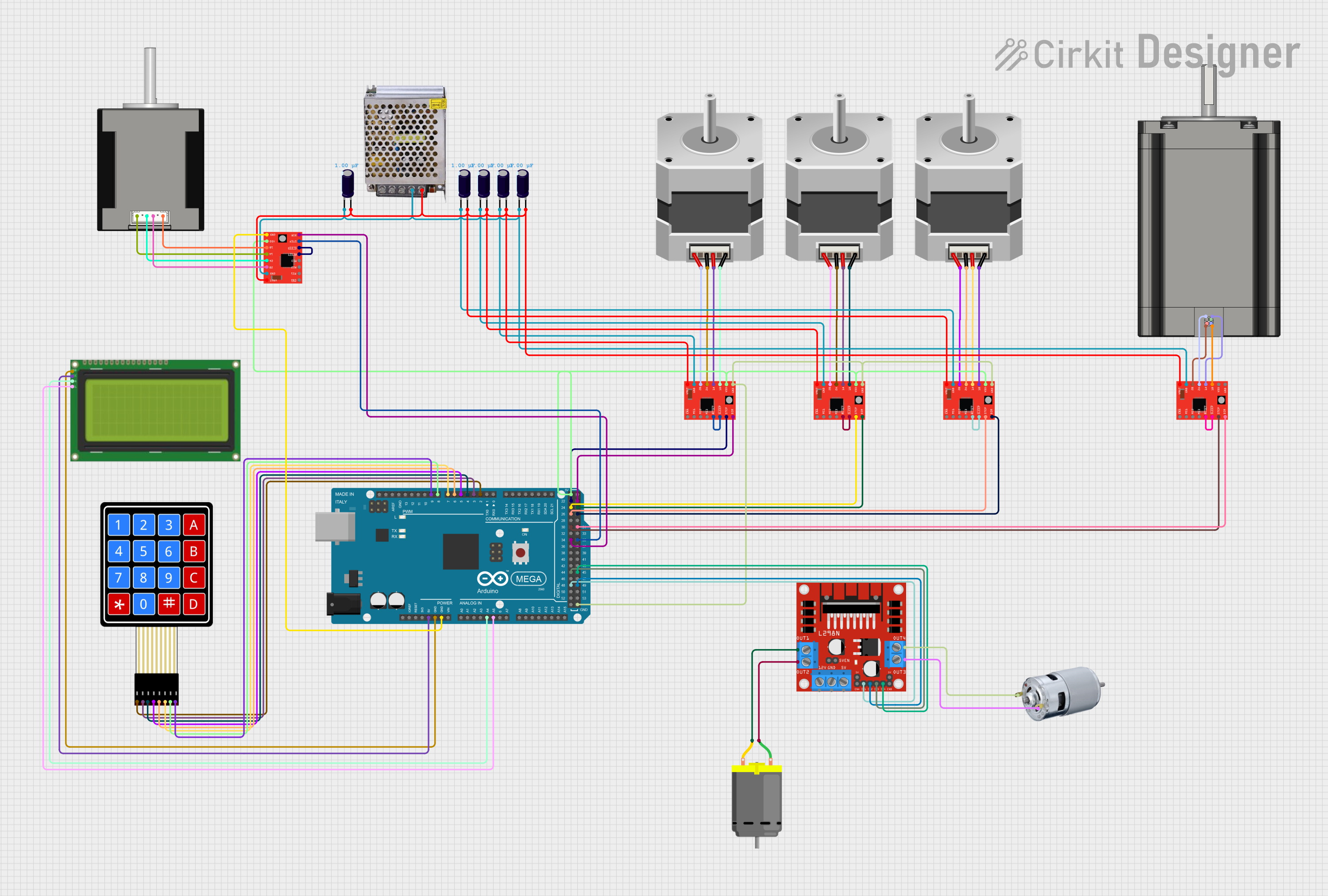
Circuit Documentation
Summary
This document provides a detailed overview of a circuit that includes an Arduino Mega 2560 microcontroller, stepper motors, DC motors, motor drivers, an LCD display, a keypad, and various other components. The circuit is designed to control multiple motors and display information on an LCD screen, with user input provided via a membrane keypad.
Component List
Arduino Mega 2560
- Description: A microcontroller board based on the ATmega2560.
- Pins: IOREF, RESET, 3V3, 5V, GND, VIN, A0-A15, D0-D53, PWM, AREF, SDA, SCL
Stepper Motor (Bipolar)
- Description: A bipolar stepper motor.
- Pins: D, B, C, A
775 Motor
- Description: A high-torque DC motor.
- Pins: positive, negative
DC Motor
- Description: A standard DC motor.
- Pins: pin 1, pin 2
A4988 Stepper Motor Driver (Red)
- Description: A driver for controlling stepper motors.
- Pins: ENABLE, MS1, MS2, MS3, RESET, SLEEP, STEP, DIR, VMOT, GND, 2B, 2A, 1A, 1B, VDD
NEMA 23
- Description: A high-torque stepper motor.
- Pins: B2 Red, B1 Blue, A2 Black, A1 Green
POWER SUPPLY 12V 5AMP
- Description: A power supply unit providing 12V at 5A.
- Pins: 220V Positive Pole (AC), 220V Negative Pole (AC), GND, GND (DC), 12V-24V Output (DC)
Electrolytic Capacitor
- Description: A capacitor with a capacitance of 0.000001 Farads.
- Pins: -, +
Lcd 20x4 i2c
- Description: A 20x4 character LCD display with I2C interface.
- Pins: GND, 5v, SCA, SCL
L298N DC motor driver
- Description: A dual H-bridge motor driver.
- Pins: OUT1, OUT2, 12V, GND, 5V, OUT3, OUT4, 5V-ENA-JMP-I, 5V-ENA-JMP-O, +5V-J1, +5V-J2, ENA, IN1, IN2, IN3, IN4, ENB
4X4 Membrane Matrix Keypad
- Description: A 4x4 matrix keypad.
- Pins: R1, R2, R3, R4, C1, C2, C3, C4
Nema 17 42-STH48
- Description: A standard NEMA 17 stepper motor.
- Pins: A2 (black), A1 Green, B2 Red, B1 Blue
Wiring Details
Arduino Mega 2560
- 5V connected to Lcd 20x4 i2c (5v)
- GND connected to Lcd 20x4 i2c (GND)
- GND connected to A4988 Stepper Motor Driver (Red) (GND)
- A4 connected to Lcd 20x4 i2c (SCA)
- A5 connected to Lcd 20x4 i2c (SCL)
- D2 PWM connected to 4X4 Membrane Matrix Keypad (R1)
- D3 PWM connected to 4X4 Membrane Matrix Keypad (R2)
- D4 PWM connected to 4X4 Membrane Matrix Keypad (R3)
- D5 PWM connected to 4X4 Membrane Matrix Keypad (R4)
- D6 PWM connected to 4X4 Membrane Matrix Keypad (C1)
- D7 PWM connected to 4X4 Membrane Matrix Keypad (C2)
- D8 PWM connected to 4X4 Membrane Matrix Keypad (C3)
- D9 PWM connected to 4X4 Membrane Matrix Keypad (C4)
- D48 connected to L298N DC motor driver (IN1)
- D44 connected to L298N DC motor driver (IN3)
- D34 connected to A4988 Stepper Motor Driver (Red) (DIR)
- D30 connected to A4988 Stepper Motor Driver (Red) (STEP)
- D26 connected to A4988 Stepper Motor Driver (Red) (STEP)
- D24 connected to A4988 Stepper Motor Driver (Red) (STEP)
- D22 connected to A4988 Stepper Motor Driver (Red) (STEP)
- 5V connected to A4988 Stepper Motor Driver (Red) (VDD)
- GND connected to A4988 Stepper Motor Driver (Red) (GND)
- D49 connected to L298N DC motor driver (IN2)
- D45 connected to L298N DC motor driver (IN4)
- D35 connected to A4988 Stepper Motor Driver (Red) (STEP)
- D31 connected to A4988 Stepper Motor Driver (Red) (DIR)
- D27 connected to A4988 Stepper Motor Driver (Red) (DIR)
- D25 connected to A4988 Stepper Motor Driver (Red) (DIR)
- D23 connected to A4988 Stepper Motor Driver (Red) (DIR)
Stepper Motor (Bipolar)
- D connected to A4988 Stepper Motor Driver (Red) (1B)
- B connected to A4988 Stepper Motor Driver (Red) (1A)
- C connected to A4988 Stepper Motor Driver (Red) (2A)
- A connected to A4988 Stepper Motor Driver (Red) (2B)
775 Motor
- positive connected to L298N DC motor driver (OUT4)
- negative connected to L298N DC motor driver (OUT3)
DC Motor
- pin 1 connected to L298N DC motor driver (OUT2)
- pin 2 connected to L298N DC motor driver (OUT1)
A4988 Stepper Motor Driver (Red)
- RESET connected to SLEEP
- VMOT connected to Electrolytic Capacitor (+)
- GND connected to Electrolytic Capacitor (-)
NEMA 23
- B2 Red connected to A4988 Stepper Motor Driver (Red) (2B)
- B1 Blue connected to A4988 Stepper Motor Driver (Red) (1B)
- A2 Black connected to A4988 Stepper Motor Driver (Red) (2A)
- A1 Green connected to A4988 Stepper Motor Driver (Red) (1A)
POWER SUPPLY 12V 5AMP
- 12V-24V Output (DC) connected to Electrolytic Capacitor (+)
- GND (DC) connected to Electrolytic Capacitor (-)
Electrolytic Capacitor
- + connected to A4988 Stepper Motor Driver (Red) (VMOT)
- - connected to A4988 Stepper Motor Driver (Red) (GND)
Lcd 20x4 i2c
- 5v connected to Arduino Mega 2560 (5V)
- GND connected to Arduino Mega 2560 (GND)
- SCA connected to Arduino Mega 2560 (A4)
- SCL connected to Arduino Mega 2560 (A5)
L298N DC motor driver
- IN1 connected to Arduino Mega 2560 (D48)
- IN2 connected to Arduino Mega 2560 (D49)
- IN3 connected to Arduino Mega 2560 (D44)
- IN4 connected to Arduino Mega 2560 (D45)
- OUT1 connected to DC Motor (pin 2)
- OUT2 connected to DC Motor (pin 1)
- OUT3 connected to 775 motor (negative)
- OUT4 connected to 775 motor (positive)
4X4 Membrane Matrix Keypad
- R1 connected to Arduino Mega 2560 (D2 PWM)
- R2 connected to Arduino Mega 2560 (D3