
Wi-Fi Controlled Smart Servo System with Arduino and ESP8266
View and Edit Project In Cirkit Designer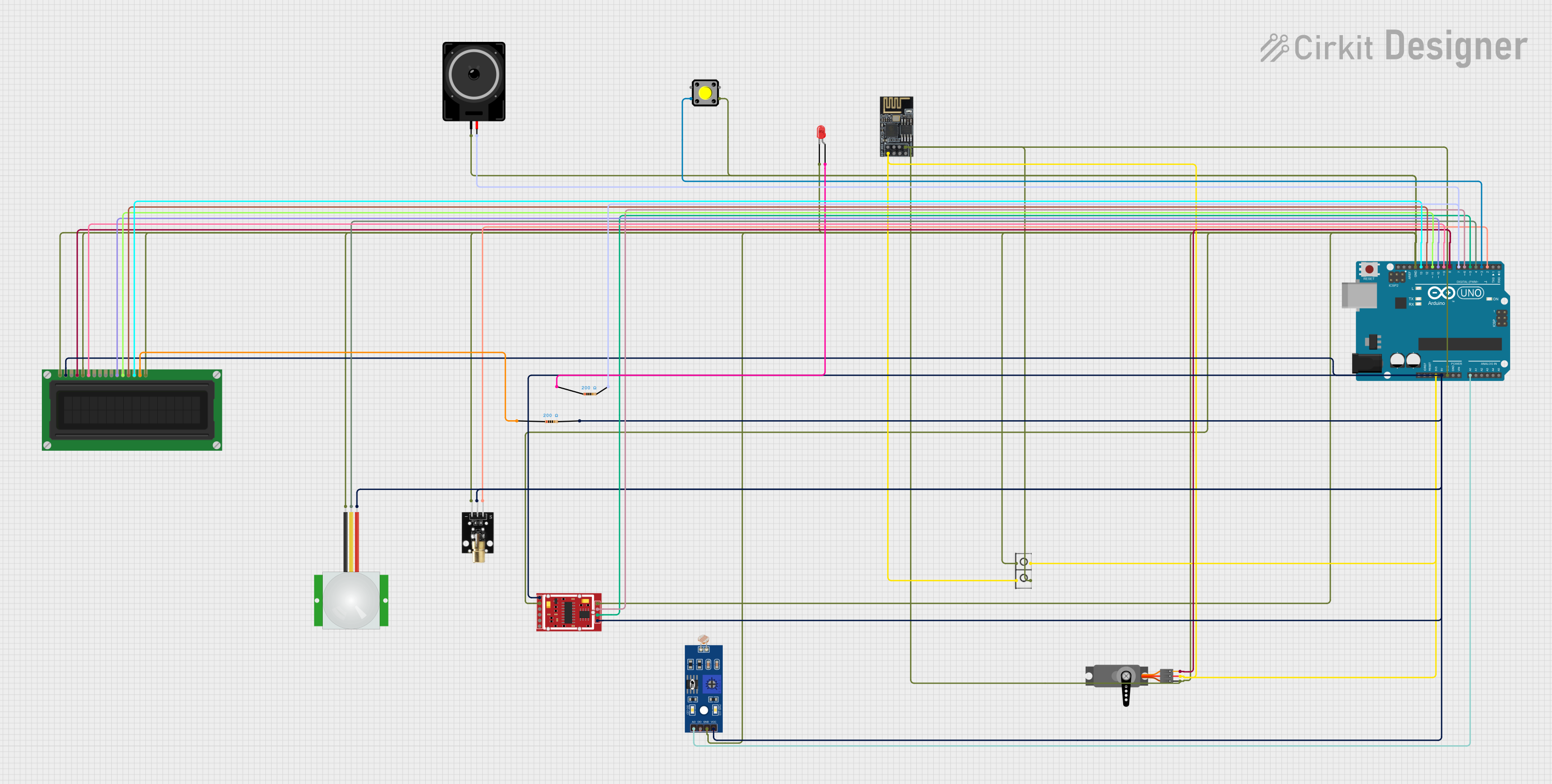
Circuit Documentation
Summary
This circuit involves multiple components including an Arduino UNO, various sensors, an LED, a servo motor, and a WiFi module. The circuit is designed to perform various tasks such as reading sensor data, controlling a servo motor, and communicating via WiFi. The Arduino UNO serves as the central microcontroller, orchestrating the operations of the connected components.
Component List
Pushbutton
- Pins: Pin 1, Pin 2, Pin 3, Pin 4
- Description: A simple pushbutton used for user input.
LED: Two Pin (red)
- Pins: Cathode, Anode
- Description: A red LED used for visual indication.
KY-008 Laser Emitter
- Pins: SIG, 5V, GND
- Description: A laser emitter module.
Servo
- Pins: GND, VCC, PWM
- Description: A servo motor used for precise control of angular position.
Resistor (200 Ohms)
- Pins: Pin 1, Pin 2
- Description: A resistor with a resistance of 200 Ohms.
LDR
- Pins: A0, D0, GND, VCC
- Description: A light-dependent resistor used to measure light intensity.
Wire Connector
- Pins: +, -
- Description: A connector for power supply.
Arduino UNO
- Pins: UNUSED, IOREF, Reset, 3.3V, 5V, GND, Vin, A0, A1, A2, A3, A4, A5, SCL, SDA, AREF, D13, D12, D11, D10, D9, D8, D7, D6, D5, D4, D3, D2, D1, D0
- Description: A microcontroller board based on the ATmega328P.
Wifi Module ESP8266-01
- Pins: RX, GPIO0, GPIO2, GND, +3V3, Reset, CH-PD Chip power down, TX
- Description: A WiFi module for wireless communication.
HX711 Weighing Sensor Module
- Pins: B-, B+, A-, A+, E-, E+, VCC, CK/TX, DO/RX, GND
- Description: A module used for weighing sensors.
PIR Sensor
- Pins: VDD, SIG, GND
- Description: A passive infrared sensor used for motion detection.
LCD Display (16 pin)
- Pins: VSS, VDD, VO, RS, R_W, E, DB0, DB1, DB2, DB3, DB4, DB5, DB6, DB7, A, K
- Description: A 16-pin LCD display.
Loudspeaker
- Pins: Pin 1, Pin 2
- Description: A loudspeaker for audio output.
Wiring Details
Pushbutton
- Pin 1: Connected to Arduino UNO D3
- Pin 2: Connected to GND
- Pin 3: Not connected
- Pin 4: Not connected
LED: Two Pin (red)
- Cathode: Connected to GND
- Anode: Connected to Resistor Pin 1
KY-008 Laser Emitter
- SIG: Connected to Arduino UNO D2
- 5V: Connected to 5V
- GND: Connected to GND
Servo
- GND: Connected to GND
- VCC: Connected to 3.3V
- PWM: Connected to Arduino UNO D9
Resistor (200 Ohms)
- Pin 1: Connected to LED Anode
- Pin 2: Connected to Loudspeaker Pin 2
LDR
- A0: Connected to Arduino UNO A0
- D0: Not connected
- GND: Connected to GND
- VCC: Connected to Resistor Pin 2
Wire Connector
- +: Connected to 3.3V
- -: Connected to GND
Arduino UNO
- 3.3V: Connected to Wire Connector +
- 5V: Connected to 5V
- GND: Connected to GND
- A0: Connected to LDR A0
- D2: Connected to KY-008 Laser Emitter SIG
- D3: Connected to Pushbutton Pin 1
- D4: Connected to PIR Sensor SIG
- D5: Connected to HX711 Weighing Sensor Module CK/TX
- D6: Connected to HX711 Weighing Sensor Module DO/RX
- D7: Connected to Loudspeaker Pin 2
- D8: Connected to Servo PWM
- D9: Connected to Servo PWM
- D10: Connected to LCD Display DB4
- D11: Connected to LCD Display DB5
- D12: Connected to LCD Display DB6
- D13: Connected to LCD Display DB7
Wifi Module ESP8266-01
- RX: Not connected
- GPIO0: Not connected
- GPIO2: Not connected
- GND: Connected to GND
- +3V3: Connected to 3.3V
- Reset: Not connected
- CH-PD Chip power down: Not connected
- TX: Not connected
HX711 Weighing Sensor Module
- B-: Not connected
- B+: Not connected
- A-: Not connected
- A+: Not connected
- E-: Connected to GND
- E+: Connected to Resistor Pin 2
- VCC: Connected to Resistor Pin 2
- CK/TX: Connected to Arduino UNO D5
- DO/RX: Connected to Arduino UNO D6
- GND: Connected to GND
PIR Sensor
- VDD: Connected to Resistor Pin 2
- SIG: Connected to Arduino UNO D4
- GND: Connected to GND
LCD Display (16 pin)
- VSS: Connected to GND
- VDD: Connected to Resistor Pin 2
- VO: Not connected
- RS: Connected to Arduino UNO D8
- R_W: Connected to GND
- E: Connected to Arduino UNO D9
- DB0: Not connected
- DB1: Not connected
- DB2: Not connected
- DB3: Not connected
- DB4: Connected to Arduino UNO D10
- DB5: Connected to Arduino UNO D11
- DB6: Connected to Arduino UNO D12
- DB7: Connected to Arduino UNO D13
- A: Connected to Resistor Pin 1
- K: Connected to GND
Loudspeaker
- Pin 1: Connected to GND
- Pin 2: Connected to Resistor Pin 2
Documented Code
Arduino UNO Code (sketch.ino)
void setup() {
  // put your setup code here, to run once:

}

void loop() {
  // put your main code here, to run repeatedly:

}
Arduino UNO Code (documentation.txt)
#include <Servo.h>
#include <SoftwareSerial.h>

Servo myServo;
SoftwareSerial esp8266(0, 1); // RX, TX

void setup() {
  myServo.attach(9); // Attach servo to pin D9
  esp8266.begin(115200); // Start communication with ESP8266
  Serial.begin(115200); // Start serial communication with the computer
}

void loop() {
  if (esp8266.available()) {
    String command = esp8266.readStringUntil('\n');
    if (command == "ROTATE_90") {
      myServo.write(90); // Rotate servo to 90 degrees
      Serial.println("Servo rotated to 90 degrees");
    }
  }
}
This documentation provides a comprehensive overview of the circuit, including a detailed list of components, their wiring connections, and the code used in the microcontroller.