
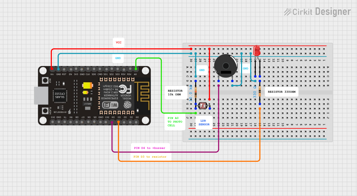
Circuit Documentation
Summary of the Circuit
This circuit is designed around the ESP8266 NodeMCU microcontroller, which serves as the central processing unit. The circuit includes a red LED, a piezo buzzer, a photocell (LDR), and two resistors of different values. The LED and the buzzer are controlled by the ESP8266 NodeMCU, and the photocell is used to sense light levels, which can be read by the microcontroller through an analog input. The circuit is powered by the VIN pin of the ESP8266 NodeMCU, which is connected to the photocell and one of the resistors.
Component List
ESP8266 NodeMCU
- Description: A WiFi-capable microcontroller module based on the ESP8266 chip.
- Pins: D0, D1, D2, D3, D4, 3V3, GND, D5, D6, D7, D8, RX, TX, A0, RSV, SD3, SD2, SD1, CMD, SD0, CLK, EN, RST, VIN
Resistor (330 Ohms)
- Description: A resistor with a resistance of 330 Ohms.
- Pins: pin1, pin2
Resistor (10 kOhms)
- Description: A resistor with a resistance of 10 kOhms.
- Pins: pin1, pin2
Piezo Buzzer
- Description: An electronic device that emits sound when an electric signal is applied.
- Pins: pin 1, pin 2
LED: Two Pin (red)
- Description: A red light-emitting diode.
- Pins: cathode, anode
Photocell (LDR)
- Description: A light-dependent resistor whose resistance changes with light intensity.
- Pins: pin 0, pin 1
Wiring Details
ESP8266 NodeMCU
- D3 is connected to the pin1 of the 330 Ohm resistor.
- GND is connected to the cathode of the red LED, pin 2 of the piezo buzzer, and pin2 of the 10 kOhm resistor.
- D4 is connected to pin 1 of the piezo buzzer.
- VIN is connected to pin 1 of the photocell (LDR).
- A0 is connected to pin 0 of the photocell (LDR) and pin1 of the 10 kOhm resistor.
Resistor (330 Ohms)
- pin1 is connected to D3 of the ESP8266 NodeMCU.
- pin2 is connected to the anode of the red LED.
Resistor (10 kOhms)
- pin1 is connected to A0 of the ESP8266 NodeMCU and pin 0 of the photocell (LDR).
- pin2 is connected to GND of the ESP8266 NodeMCU.
Piezo Buzzer
- pin 1 is connected to D4 of the ESP8266 NodeMCU.
- pin 2 is connected to GND of the ESP8266 NodeMCU.
LED: Two Pin (red)
- cathode is connected to GND of the ESP8266 NodeMCU.
- anode is connected to pin2 of the 330 Ohm resistor.
Photocell (LDR)
- pin 1 is connected to VIN of the ESP8266 NodeMCU.
- pin 0 is connected to A0 of the ESP8266 NodeMCU and pin1 of the 10 kOhm resistor.
Documented Code
No code has been provided for the microcontroller. The documentation of the code would typically include a description of the functionality implemented in the code, along with comments explaining the purpose of different sections of the code. Since no code is available, this section cannot be completed.