
Circuit Documentation
Summary
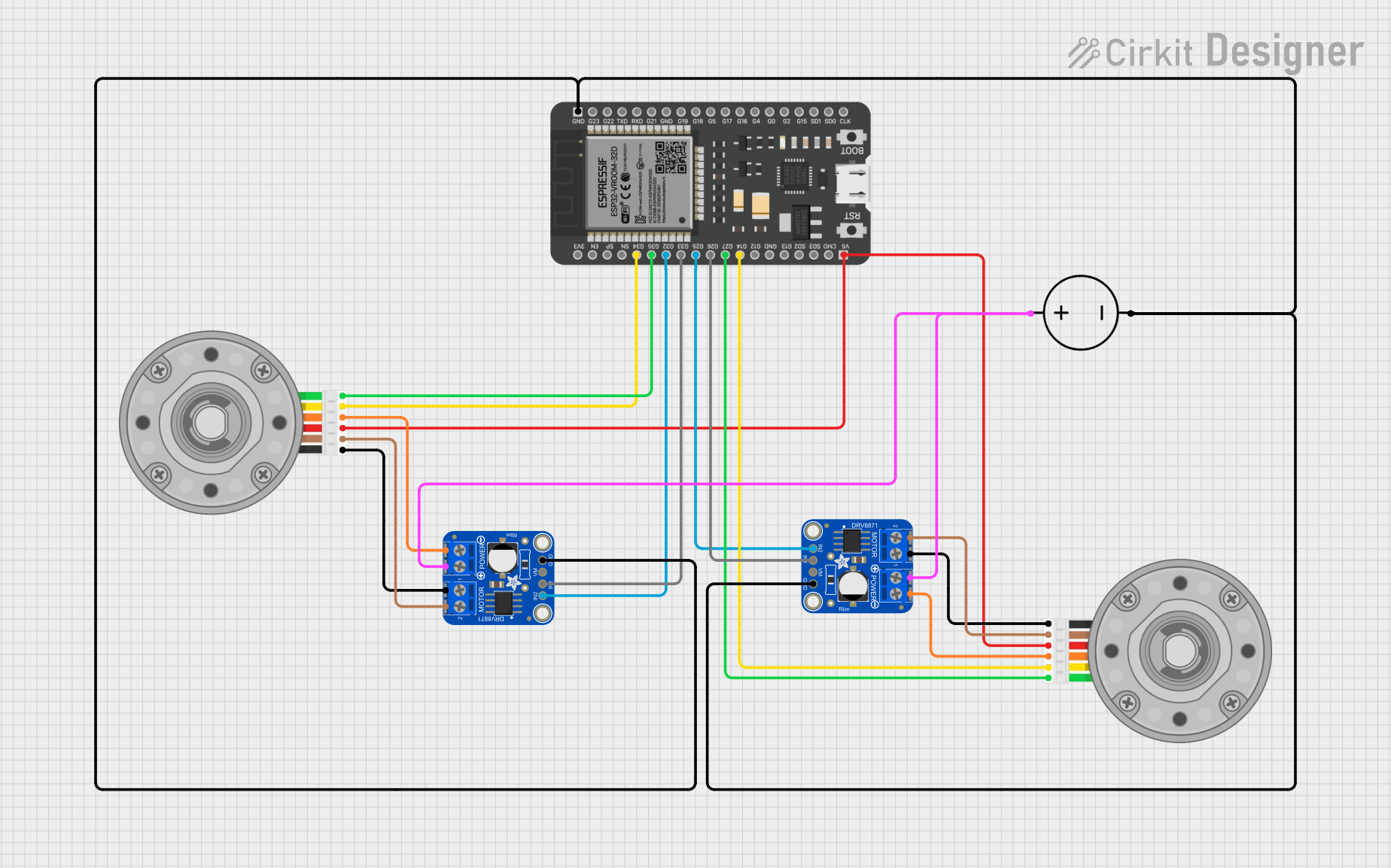
This circuit is designed to control two DC motors with encoders using an ESP32 microcontroller and two Adafruit DRV8871 motor drivers. The ESP32 is responsible for driving the motors via the motor drivers and reading the encoder signals to determine the position and speed of the motors. The circuit is powered by a DC power source.
Component List
ESP32 - 38 pins
- Description: A microcontroller with WiFi and Bluetooth capabilities and a variety of GPIO pins.
- Purpose: Acts as the central processing unit for controlling the motor drivers and reading encoder signals.
DC Motor with Encoder (x2)
- Description: A DC motor with an integrated quadrature encoder for position and speed feedback.
- Purpose: Provides mechanical actuation for the system.
Adafruit DRV8871 Motor Driver (x2)
- Description: A motor driver capable of driving a single DC motor.
- Purpose: Controls the direction and speed of the connected DC motor.
DC Power Source
- Description: Provides the necessary power to drive the motors and the electronics.
- Purpose: Supplies power to the motor drivers and the ESP32 microcontroller.
Wiring Details
ESP32 - 38 pins
GNDconnected to the ground net of the circuit.G33connected toIN1of the first Adafruit DRV8871 motor driver.G32connected toIN2of the first Adafruit DRV8871 motor driver.G26connected toIN1of the second Adafruit DRV8871 motor driver.G25connected toIN2of the second Adafruit DRV8871 motor driver.G35connected toEncoder Bof the first DC Motor with Encoder.G34connected toEncoder Aof the first DC Motor with Encoder.G27connected toEncoder Bof the second DC Motor with Encoder.G14connected toEncoder Aof the second DC Motor with Encoder.5Vconnected toVCCof both DC Motors with Encoder.
DC Motor with Encoder
Encoder BandEncoder Aconnected to the ESP32 for feedback.GNDconnected to the ground net of the circuit.VCCconnected to the5Voutput from the ESP32.Motor +veandMotor -veconnected toOUT2andOUT1respectively of the corresponding Adafruit DRV8871 motor driver.
Adafruit DRV8871 Motor Driver
GNDconnected to the ground net of the circuit.VMOTORconnected to the positive terminal of the DC Power Source.IN1andIN2connected to the corresponding GPIO pins on the ESP32 for motor control.OUT1andOUT2connected to theMotor -veandMotor +vepins of the corresponding DC Motor with Encoder.
DC Power Source
Groundconnected to the ground net of the circuit.Positiveconnected toVMOTORof both Adafruit DRV8871 motor drivers.
Documented Code
There is no code provided for the microcontroller. The code would typically include initialization of GPIO pins, PWM setup for motor control, interrupt configuration for encoder reading, and the main control loop for driving the motors based on the desired logic.