
Arduino Nano-Based Dual 4x4 Keypad Interface with LCD Display and NRF24L01 Wireless Communication
View and Edit Project In Cirkit Designer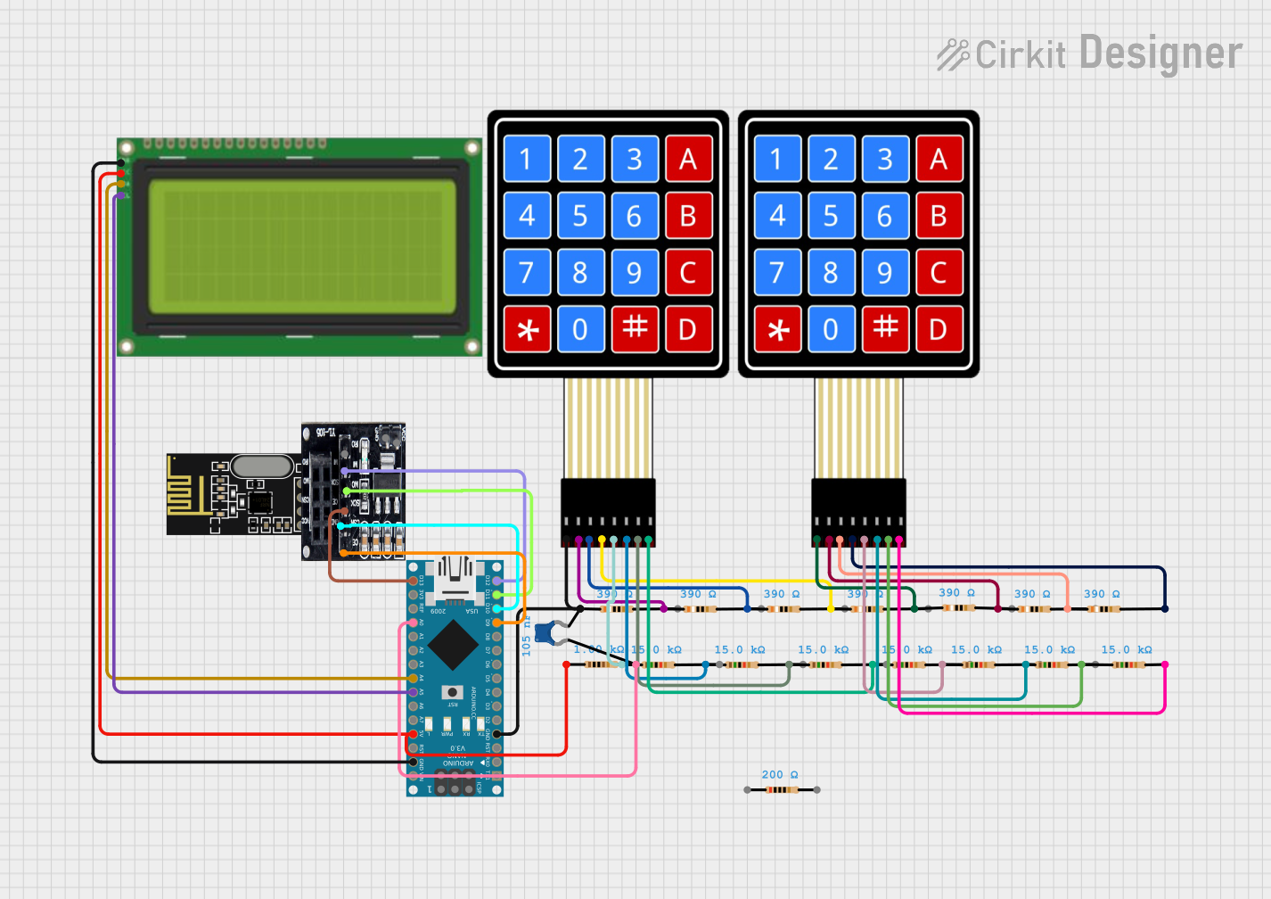
Circuit Documentation
Summary
This circuit involves an Arduino Nano microcontroller interfacing with various components including resistors, a 4x4 membrane matrix keypad, an NRF24L01 wireless module, an LCD display, and a ceramic capacitor. The circuit is designed to handle input from the keypad, display information on the LCD, and communicate wirelessly using the NRF24L01 module.
Component List
Resistor
- Description: A passive electrical component that implements electrical resistance as a circuit element.
- Pins: pin1, pin2
- Properties:
- Resistance: 390 Ohms
- Resistance: 15,000 Ohms
- Resistance: 1,000 Ohms
- Resistance: 200 Ohms
4X4 Membrane Matrix Keypad
- Description: A keypad with 16 keys arranged in a 4x4 matrix.
- Pins: R1, R2, R3, R4, C1, C2, C3, C4
Ceramic Capacitor
- Description: A capacitor with a ceramic dielectric.
- Pins: pin0, pin1
- Properties:
- Capacitance: 1.05e-7 Farads
Arduino Nano
- Description: A small, complete, and breadboard-friendly board based on the ATmega328P.
- Pins: D1/TX, D0/RX, RESET, GND, D2, D3, D4, D5, D6, D7, D8, D9, D10, D11/MOSI, D12/MISO, VIN, 5V, A7, A6, A5, A4, A3, A2, A1, A0, AREF, 3V3, D13/SCK
NRF24L01
- Description: A wireless transceiver module.
- Pins: IRQ (not used), MOSI, CSN, VCC (3V), GND, CE, SCK, MISO
NRF24L01 Adapter
- Description: An adapter for the NRF24L01 module.
- Pins: CE, CSN, SCK, MOSI, MISO, IRQ, VCC, GND
LCD 20x4 I2C
- Description: A 20x4 character LCD display with I2C interface.
- Pins: GND, 5V, SCA, SCL
Wiring Details
Resistor
390 Ohms:
- pin1 connected to GND of Arduino Nano and R1 of 4X4 Membrane Matrix Keypad
- pin1 connected to R2 of 4X4 Membrane Matrix Keypad
- pin1 connected to R3 of 4X4 Membrane Matrix Keypad
- pin1 connected to R4 of 4X4 Membrane Matrix Keypad
- pin1 connected to R1 of 4X4 Membrane Matrix Keypad (second instance)
- pin1 connected to R2 of 4X4 Membrane Matrix Keypad (second instance)
- pin1 connected to R3 of 4X4 Membrane Matrix Keypad (second instance)
- pin2 connected to R4 of 4X4 Membrane Matrix Keypad (second instance)
15,000 Ohms:
- pin1 connected to C4 of 4X4 Membrane Matrix Keypad
- pin1 connected to C2 of 4X4 Membrane Matrix Keypad
- pin1 connected to C1 of 4X4 Membrane Matrix Keypad (second instance)
- pin1 connected to C3 of 4X4 Membrane Matrix Keypad
- pin1 connected to C2 of 4X4 Membrane Matrix Keypad (second instance)
- pin1 connected to C3 of 4X4 Membrane Matrix Keypad (second instance)
- pin2 connected to C4 of 4X4 Membrane Matrix Keypad (second instance)
- pin1 connected to C1 of 4X4 Membrane Matrix Keypad
1,000 Ohms:
- pin1 connected to 5V of Arduino Nano and 5V of LCD 20x4 I2C
- pin2 connected to A0 of Arduino Nano
200 Ohms:
- pin1 connected to 5V of Arduino Nano and 5V of LCD 20x4 I2C
- pin2 connected to A0 of Arduino Nano
4X4 Membrane Matrix Keypad
First Instance:
- R1 connected to GND of Arduino Nano and pin1 of 390 Ohms Resistor
- R2 connected to pin1 of 390 Ohms Resistor
- R3 connected to pin1 of 390 Ohms Resistor
- R4 connected to pin1 of 390 Ohms Resistor
- C1 connected to pin1 of 15,000 Ohms Resistor
- C2 connected to pin1 of 15,000 Ohms Resistor
- C3 connected to pin1 of 15,000 Ohms Resistor
- C4 connected to pin1 of 15,000 Ohms Resistor
Second Instance:
- R1 connected to pin1 of 390 Ohms Resistor
- R2 connected to pin1 of 390 Ohms Resistor
- R3 connected to pin1 of 390 Ohms Resistor
- R4 connected to pin2 of 390 Ohms Resistor
- C1 connected to pin1 of 15,000 Ohms Resistor
- C2 connected to pin1 of 15,000 Ohms Resistor
- C3 connected to pin1 of 15,000 Ohms Resistor
- C4 connected to pin2 of 15,000 Ohms Resistor
Ceramic Capacitor
- pin0 and pin1 are not connected in the provided net list.
Arduino Nano
- GND connected to GND of LCD 20x4 I2C
- 5V connected to 5V of LCD 20x4 I2C
- A0 connected to pin2 of 1,000 Ohms Resistor
- D9 connected to CE of NRF24L01 Adapter
- D10 connected to CSN of NRF24L01 Adapter
- D11/MOSI connected to MOSI of NRF24L01 Adapter
- D12/MISO connected to MISO of NRF24L01 Adapter
- D13/SCK connected to SCK of NRF24L01 Adapter
- A4 connected to SCA of LCD 20x4 I2C
- A5 connected to SCL of LCD 20x4 I2C
NRF24L01
- Connected through NRF24L01 Adapter
NRF24L01 Adapter
- CE connected to D9 of Arduino Nano
- CSN connected to D10 of Arduino Nano
- SCK connected to D13/SCK of Arduino Nano
- MOSI connected to D11/MOSI of Arduino Nano
- MISO connected to D12/MISO of Arduino Nano
LCD 20x4 I2C
- GND connected to GND of Arduino Nano
- 5V connected to 5V of Arduino Nano
- SCA connected to A4 of Arduino Nano
- SCL connected to A5 of Arduino Nano
Documented Code
Arduino Nano Code
void setup() {
  // put your setup code here, to run once:

}

void loop() {
  // put your main code here, to run repeatedly:

}
This code is a basic template for the Arduino Nano, with empty setup and loop functions. You can add your specific functionality within these functions to control the connected components.