
Battery-Powered Game Controller with SparkFun Pro Micro and Raspberry Pi 4B
View and Edit Project In Cirkit Designer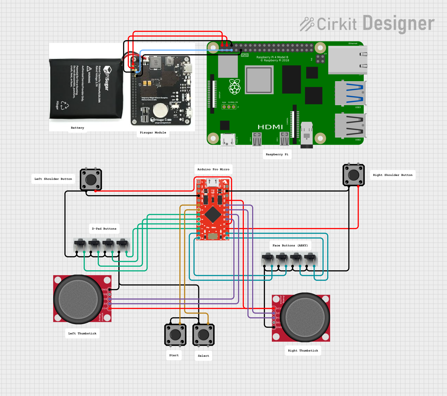
Circuit Documentation
Summary
This circuit is designed to interface a SparkFun Pro Micro microcontroller with various tactile pushbuttons and analog joysticks. The circuit also includes a Raspberry Pi 4B powered by a Pisugar S Pro. The SparkFun Pro Micro reads inputs from the buttons and joysticks and processes them to control a gamepad. The Raspberry Pi 4B is powered by the Pisugar S Pro and is connected to the circuit for additional functionality.
Component List
SparkFun Pro Micro
- Description: A compact microcontroller board based on the ATmega32U4.
- Pins: RAW, GND, RESET, VCC, A3, A2, A1, A0, SCK, MISO, MOSI, D10, D9, D8, D7, D6, D5, D4, D3, D2, RXI, TXO
Tactile Switch Buttons - 12mm Square
- Description: A 12mm square tactile switch button.
- Pins: 3, 1, 4, 2
Silicone Tactile Pushbutton
- Description: A silicone tactile pushbutton.
- Pins: 1, 2
Raspberry Pi 4B
- Description: A powerful single-board computer.
- Pins: 3V3, 5V, GPIO2, GPIO3, GND, GPIO4, GPIO14, GPIO15, GPIO17, GPIO18, GPIO27, GPIO22, GPIO23, GPIO24, GPIO10, GPIO9, GPIO25, GPIO11, GPIO8, GPIO7, ID_SD, GPIO5, GPIO6, GPIO12, GPIO13, GPIO19, GPIO16, GPIO26, GPIO20, GPIO21, ID_SC, TR01_TAP, TR00_TAP, TR03_TAP, TR02_TAP, RUN, GLOBAL_EN
Pisugar S Pro
- Description: A battery management system for the Raspberry Pi.
- Pins: None
Analog Joystick (Wokwi Compatible)
- Description: An analog joystick compatible with Wokwi.
- Pins: VCC, VERT, HORZ, SEL, GND
Wiring Details
SparkFun Pro Micro
- GND: Connected to GND of various components.
- VCC: Connected to VCC of Analog Joysticks.
- A3: Connected to VERT of Analog Joystick.
- A2: Connected to HORZ of Analog Joystick.
- A1: Connected to VERT of another Analog Joystick.
- A0: Connected to HORZ of another Analog Joystick.
- SCK: Connected to pin 4 of Tactile Switch Button.
- MISO: Connected to pin 4 of another Tactile Switch Button.
- MOSI: Connected to pin 2 of Silicone Tactile Pushbutton.
- D10: Connected to pin 2 of another Silicone Tactile Pushbutton.
- D9: Connected to pin 2 of another Silicone Tactile Pushbutton.
- D8: Connected to pin 2 of another Silicone Tactile Pushbutton.
- D7: Connected to pin 2 of another Silicone Tactile Pushbutton.
- D6: Connected to pin 2 of another Silicone Tactile Pushbutton.
- D5: Connected to pin 2 of another Silicone Tactile Pushbutton.
- D4: Connected to pin 2 of another Silicone Tactile Pushbutton.
- D3: Connected to pin 2 of another Tactile Switch Button.
- D2: Connected to pin 2 of another Tactile Switch Button.
Tactile Switch Buttons - 12mm Square
- Pin 3: Connected to GND.
- Pin 1: Connected to GND.
- Pin 4: Connected to SCK of SparkFun Pro Micro.
- Pin 2: Connected to D3 of SparkFun Pro Micro.
Silicone Tactile Pushbutton
- Pin 1: Connected to GND.
- Pin 2: Connected to various digital pins of SparkFun Pro Micro (D10, D9, D8, D7, D6, D5, D4).
Raspberry Pi 4B
- 5V: Connected to Pisugar S Pro.
- GPIO3: Connected to Pisugar S Pro.
- GND: Connected to Pisugar S Pro.
Pisugar S Pro
- 5V: Connected to 5V of Raspberry Pi 4B.
- GPIO3: Connected to GPIO3 of Raspberry Pi 4B.
- GND: Connected to GND of Raspberry Pi 4B.
Analog Joystick (Wokwi Compatible)
- VCC: Connected to VCC of SparkFun Pro Micro.
- VERT: Connected to A3 of SparkFun Pro Micro.
- HORZ: Connected to A2 of SparkFun Pro Micro.
- SEL: Not connected.
- GND: Connected to GND.
Code Documentation
#include <Gamepad.h>

int rightXcenter = 500;
int rightYcenter = 500;
int leftXcenter = 500;
int leftYcenter = 500;
double multiplierRX = 0.254; //127 / 500
double multiplierRY = 0.254;
double multiplierLX = 0.254;
double multiplierLY = 0.254;

Gamepad gp;

void setup() {
  pinMode(A0, INPUT);
  pinMode(A1, INPUT);
  pinMode(A2, INPUT);
  pinMode(A3, INPUT);
  pinMode(2, INPUT_PULLUP); // Start
  pinMode(3, INPUT_PULLUP); // Select
  pinMode(4, INPUT_PULLUP); // UP
  pinMode(5, INPUT_PULLUP); // DOWN
  pinMode(6, INPUT_PULLUP); // LEFT
  pinMode(7, INPUT_PULLUP); // RIGHT
  pinMode(8, INPUT_PULLUP); // Y
  pinMode(9, INPUT_PULLUP); // X
  pinMode(10, INPUT_PULLUP); // A
  pinMode(16, INPUT_PULLUP); // B
  pinMode(15, INPUT_PULLUP); // R
  pinMode(14, INPUT_PULLUP); // L

  calibrate();
}

void loop() {
  int lx, ly, rx, ry;
  lx = analogRead(A3);
  ly = analogRead(A2);
  rx = analogRead(A1);
  ry = analogRead(A0);
  // We need to convert a 0-1000 to -127 - 127
  lx = floor((lx - leftXcenter) * multiplierLX);
  ly = floor((ly - leftYcenter) * multiplierLY);
  rx = floor((rx - rightXcenter) * multiplierRX);
  ry = floor((ry - rightYcenter) * multiplierRY);
  if (lx > 127) lx = 127;
  if (ly > 127) ly = 127;
  if (rx > 127) rx = 127;
  if (ry > 127) ry = 127;
  gp.setLeftXaxis(lx);
  gp.setRightXaxis(rx);
  gp.setLeftYaxis(ly);
  gp.setRightYaxis(ry);

  int START, SELECT, UP, DOWN, LEFT, RIGHT, X, Y, A, B, R, L;
  UP = digitalRead(4);
  DOWN = digitalRead(5);
  LEFT = digitalRead(6);
  RIGHT = digitalRead(7);
  X = digitalRead(8);
  Y = digitalRead(9);
  A = digitalRead(10);
  B = digitalRead(16);
  R = digitalRead(15);
  L = digitalRead(14);
  START = digitalRead(2);
  SELECT = digitalRead(3);

  if (UP == LOW)
    gp.setButtonState(0, true);
  else
    gp.setButtonState(0, false);

  if (DOWN == LOW)
    gp.setButtonState(1, true);
  else
    gp.setButtonState(1, false);

  if (LEFT == LOW)
    gp.setButtonState(2, true);
  else
    gp.setButtonState(2, false);

  if (RIGHT == LOW)
    gp.setButtonState(3, true);
  else
    gp.setButtonState(3, false);

  if (X == LOW)
    gp.setButtonState(4, true);
  else
    gp.setButtonState(4, false);

  if (Y == LOW)
    gp.setButtonState(5, true);
  else
    gp.setButtonState(5, false);

  if (A == LOW)
    gp.setButtonState(6, true);
  else
    gp.setButtonState(6, false);

  if (B == LOW)
    gp.setButtonState(7, true);
  else
    gp.setButtonState(7, false);

  if (R == LOW)
    gp