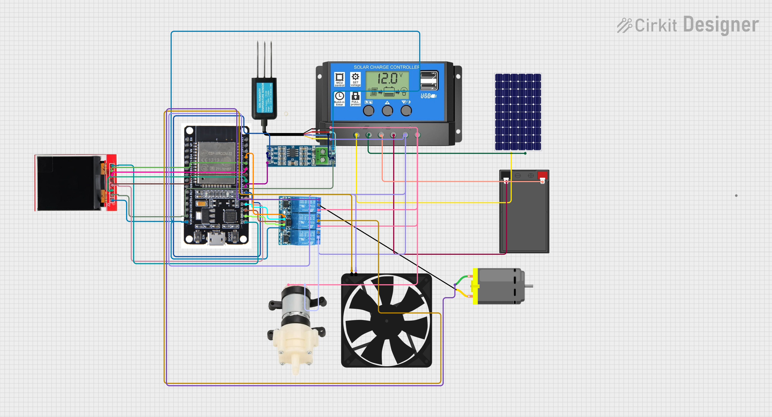
Solar-Powered Automated Irrigation System with ESP32 and Soil Moisture Sensing

Circuit Documentation
Summary
This circuit is designed to utilize solar power to operate various components including a fan, a mini diaphragm water pump, a DC motor, and a soil moisture sensor. The solar power is managed by a solar charge controller that charges a battery and provides power to the load. The system's brain is an ESP32 microcontroller, which interfaces with an RS-485 module for sensor communication, a TFT LCD display for user interface, and a 3-channel relay to control power to the fan, pump, and motor. The soil moisture sensor's data is used to determine the watering needs, and the ESP32 can display the status and control the watering system accordingly.
Component List
Solar Charge Controller
- Description: Manages the charging of the battery from the solar panel and provides power to the load.
- Pins: Solar Cell +, Solar Cell -, Battery +, Battery -, Load +, Load -
Solar Panel
- Description: Converts sunlight into electrical energy to power the system and charge the battery.
- Pins: +, -
Soil Moisture Sensor
- Description: Measures the moisture level of the soil.
- Pins: RS485 - A, VCC, GND, RS485 - B
ESP32
- Description: A microcontroller with Wi-Fi capabilities that serves as the central processing unit of the circuit.
- Pins: EN, VP, VN, D34, D35, D32, D33, D25, D26, D27, D14, D12, D13, GND, VIN, 3V3, D15, D2, D4, RX2, TX2, D5, D18, D19, D21, RX0, TX0, D22, D23, BOOT
RS-485 Module
- Description: Allows for long-distance communication between the ESP32 and the soil moisture sensor.
- Pins: VCC, B, A, GND, RO, RE, DE, DI
Battery
- Description: Stores electrical energy for use by the circuit when solar power is not available.
- Pins: -, +
TFT LCD Display ST7735S
- Description: A small display to show information and statuses from the ESP32.
- Pins: Vcc, GND, CS, RESET, A0, SDA, SCK, LED
3 Channel Relay 5V
- Description: Allows the ESP32 to control high power devices such as the fan, water pump, and DC motor.
- Pins: COMMON, NO, NC, VCC, GND, CH3, CH2, CH1
Fan
- Description: Provides air circulation.
- Pins: GND, 5V
Mini Diaphragm Water Pump
- Description: Pumps water when activated by the relay.
- Pins: Positive (+), Negative (-)
DC Motor
- Description: Converts electrical energy into mechanical motion.
- Pins: pin 1, pin 2
Wiring Details
Solar Charge Controller
- Solar Cell +: Connected to Solar Panel +
- Solar Cell -: Connected to Solar Panel -
- Battery +: Connected to Battery +
- Battery -: Connected to Battery -
- Load +: Connected to Fan 5V, 3 Channel Relay 5V NO, Soil Moisture Sensor RS485 - A
- Load -: Connected to Mini Diaphragm Water Pump Negative (-), 3 Channel Relay 5V NO, Soil Moisture Sensor GND
Solar Panel
- +: Connected to Solar Charge Controller Solar Cell +
- -: Connected to Solar Charge Controller Solar Cell -
Soil Moisture Sensor
- RS485 - A: Connected to Solar Charge Controller Load +
- VCC: Connected to RS-485 Module VCC
- GND: Connected to Solar Charge Controller Load -
- RS485 - B: Connected to RS-485 Module A
ESP32
- GND: Connected to TFT LCD Display GND, RS-485 Module GND, 3 Channel Relay 5V GND
- VIN: Connected to TFT LCD Display Vcc, RS-485 Module VCC, 3 Channel Relay 5V VCC
- 3V3: Connected to TFT LCD Display LED
- D15: Connected to 3 Channel Relay 5V CH3
- D2: Connected to 3 Channel Relay 5V CH2
- D4: Connected to TFT LCD Display RESET
- RX2: Connected to RS-485 Module RO
- TX2: Connected to RS-485 Module DI
- D5: Connected to TFT LCD Display CS
- D18: Connected to TFT LCD Display A0
- D19: Connected to TFT LCD Display SDA
- D21: Connected to TFT LCD Display SCK
- RX0: Connected to 3 Channel Relay 5V CH1
RS-485 Module
- VCC: Connected to Soil Moisture Sensor VCC
- B: Connected to Soil Moisture Sensor RS485 - A
- A: Connected to Soil Moisture Sensor RS485 - B
- GND: Connected to Soil Moisture Sensor GND
- RO: Connected to ESP32 RX2
- RE: Connected to RS-485 Module DE
- DE: Connected to RS-485 Module RE
- DI: Connected to ESP32 TX2
Battery
- +: Connected to Solar Charge Controller Battery +
- -: Connected to Solar Charge Controller Battery -
TFT LCD Display ST7735S
- GND: Connected to ESP32 GND
- Vcc: Connected to ESP32 VIN
- CS: Connected to ESP32 D5
- RESET: Connected to ESP32 D4
- A0: Connected to ESP32 D18
- SDA: Connected to ESP32 D19
- SCK: Connected to ESP32 D21
- LED: Connected to ESP32 3V3
3 Channel Relay 5V
- COMMON: Connected to Fan GND, Mini Diaphragm Water Pump Positive (+)
- NO: Connected to Solar Charge Controller Load +, Mini Diaphragm Water Pump Negative (-)
- NC: Connected to DC Motor pin 1
- VCC: Connected to ESP32 VIN
- GND: Connected to ESP32 GND
- CH3: Connected to ESP32 D15
- CH2: Connected to ESP32 D2
- CH1: Connected to ESP32 RX0
Fan
- GND: Connected to 3 Channel Relay 5V COMMON
- 5V: Connected to Solar Charge Controller Load +
Mini Diaphragm Water Pump
- Positive (+): Connected to 3 Channel Relay 5V COMMON
- Negative (-): Connected to Solar Charge Controller Load -
DC Motor
- pin 1: Connected to 3 Channel Relay 5V NC
- pin 2: Not connected
Documented Code
No code was provided for the microcontroller(s) in the circuit. If code is available, it should be documented here with explanations for each function and routine, including setup and loop functions, interrupt service routines, and any communication protocol implementations.