Microcontroller-Driven Motor Control System with LCD Interface and Thermal Management
Circuit Documentation
Summary
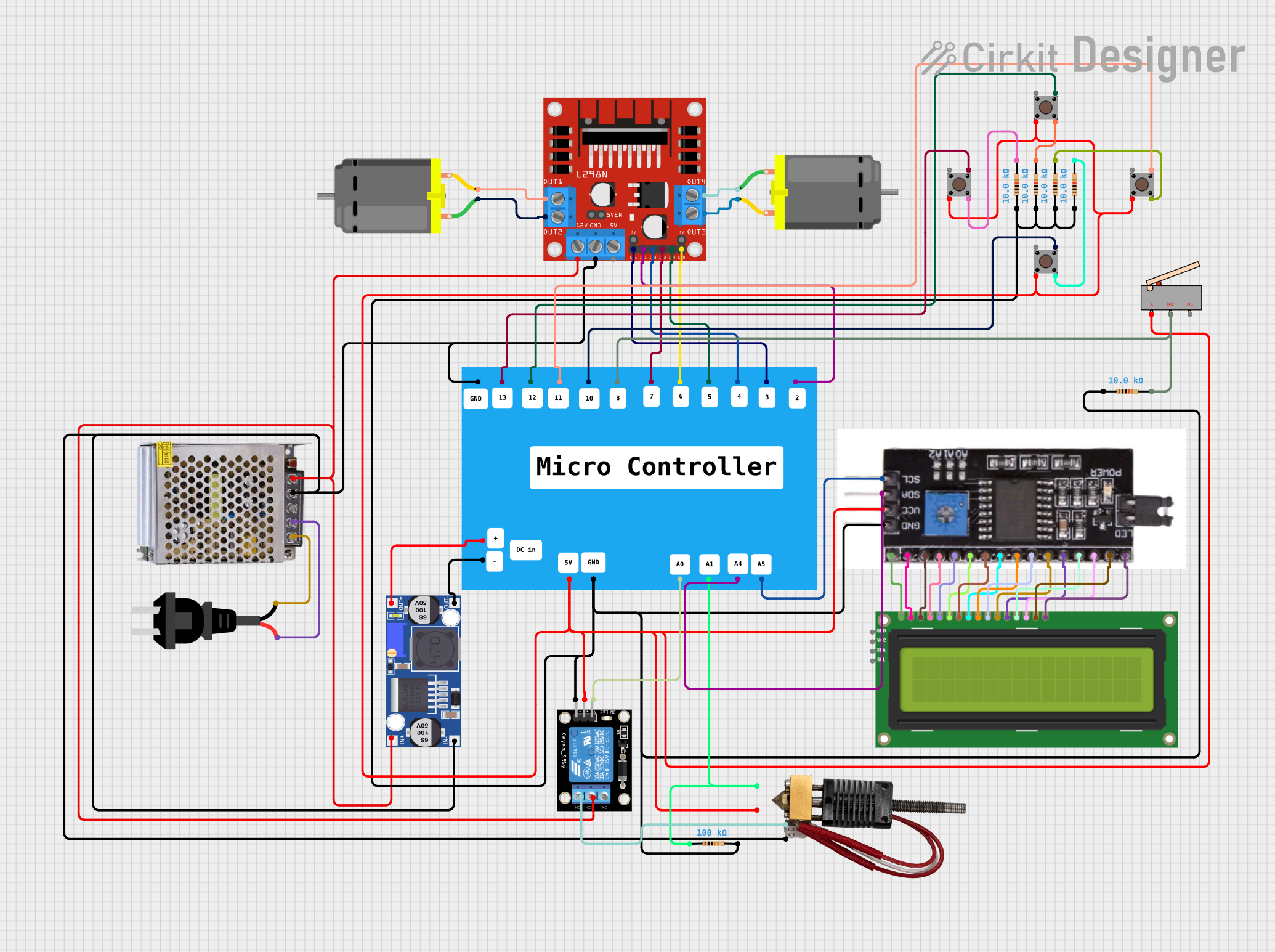
The circuit in question appears to be a control system that utilizes a microcontroller to drive two DC motors via an L298N motor driver. It also includes a relay module to control a hot end device, an I2C module connected to an I2C LCD 16x2 screen for display purposes, and multiple pushbuttons with resistors that likely serve as input devices. The power supply is a 12V 5A unit, which is regulated down for the microcontroller using a buck converter. There are also limit switches that may serve as endstops or safety switches.
Component List
DC Motors
- Description: Electric motors that convert DC electrical energy into mechanical energy.
- Purpose: To provide actuation for movement in the system.
AC Source
- Description: A source of alternating current (AC) electrical power.
- Purpose: To supply power to the 12V 5A power supply.
I2C Module
- Description: An interface module that allows communication over the I2C protocol.
- Purpose: To facilitate communication between the microcontroller and the I2C LCD screen.
I2C LCD 16x2 Screen
- Description: A liquid crystal display capable of showing 16 characters per line on 2 lines.
- Purpose: To display status information or messages from the microcontroller.
Relay Module 1 Channel
- Description: An electrically operated switch that allows a low-power signal to control a higher power circuit.
- Purpose: To control the on/off state of the hot end device.
Resistor
- Description: A passive two-terminal electrical component that implements electrical resistance as a circuit element.
- Purpose: To limit current or divide voltages in the circuit.
Pushbutton
- Description: A simple switch mechanism for controlling some aspect of a machine or a process.
- Purpose: To provide user input to the microcontroller.
L298N DC Motor Driver
- Description: A dual H-bridge motor driver that can drive two DC motors.
- Purpose: To control the speed and direction of the DC motors.
Power Supply 12V 5A
- Description: A power supply unit that converts AC to 12V DC.
- Purpose: To provide power to the motor driver, relay module, and buck converter.
Hot End
- Description: A component used in 3D printers that melts the filament for printing.
- Purpose: To act as the printing head in a 3D printer setup.
Buck Converter
- Description: A DC-to-DC power converter that steps down voltage from its input to its output.
- Purpose: To provide the appropriate voltage level for the microcontroller.
Limit Switch
- Description: An electromechanical device that consists of an actuator mechanically linked to a set of contacts.
- Purpose: To detect the presence or absence of an object or to detect the limit of motion of an object.
Microcontroller
- Description: A compact integrated circuit designed to govern a specific operation in an embedded system.
- Purpose: To control the logic and decision-making of the circuit.
Wiring Details
DC Motors
- Motor 1 connected to L298N DC motor driver OUT1 and OUT2.
- Motor 2 connected to L298N DC motor driver OUT3 and OUT4.
AC Source
- Connected to the 220V input of the Power Supply 12V 5A.
I2C Module
- Connected to the I2C LCD 16x2 Screen for all corresponding pins (VSS, VO, RS, RW, E, DB0-DB7, LEDA, LEDK, GND, VCC, SDA, SCL, VDD).
I2C LCD 16x2 Screen
- Wired to the I2C Module for communication and power.
Relay Module 1 Channel
- COM connected to the 12V power supply.
- NO connected to the Hot End "+".
- GND connected to the common ground net.
- S connected to the Microcontroller A0 pin.
- 5V connected to the 5V net.
Resistor
- Multiple resistors used, likely for pull-up/pull-down configurations on buttons or as current limiting resistors.
Pushbuttons
- Connected to various pins on the Microcontroller with resistors in the circuit, likely for debouncing or pull-up/pull-down configurations.
L298N DC Motor Driver
- 12V and GND connected to the Power Supply 12V 5A.
- Motor outputs connected to the DC Motors.
- Control inputs (ENA, ENB, IN1, IN2, IN3, IN4) connected to the Microcontroller.
Power Supply 12V 5A
- AC input connected to the AC Source.
- 12V DC output connected to the L298N DC motor driver, Relay Module, and Buck Converter.
Hot End
- "+" connected to the Relay Module NO contact.
- "-" connected to the common ground net.
- "T+" connected to the Microcontroller A1 pin through a resistor.
- "T-" connected to the common ground net.
Buck Converter
- IN+ and IN- connected to the 12V power supply.
- OUT+ and OUT- connected to the Microcontroller DC input pins.
Limit Switch
- C connected to the 5V net.
- NO connected to the Microcontroller pin 8 and a resistor.
Documented Code
There is no code provided for the microcontroller. The expected code would handle input from the pushbuttons, drive the motors via the L298N motor driver, control the relay for the hot end, and update the display on the I2C LCD screen based on the system status.