
Wi-Fi Controlled LED Indicator with Wemos D1 Mini and Pushbutton
View and Edit Project In Cirkit Designer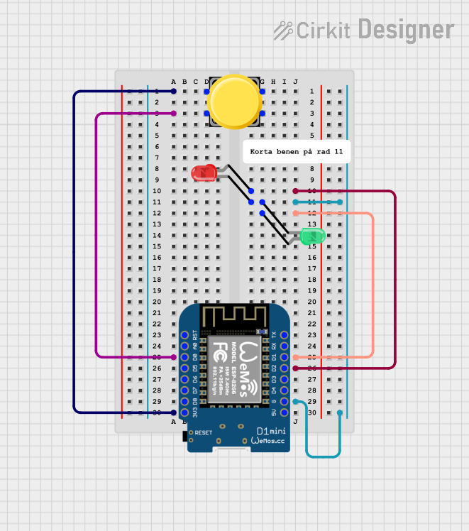
Circuit Documentation
Summary
This circuit consists of a Wemos D1 Mini microcontroller, a pushbutton, and two LEDs (one green and one red). The pushbutton is used to interact with the microcontroller, which in turn controls the LEDs. The green LED is connected to pin D1 of the Wemos D1 Mini, and the red LED is connected to pin D2. The pushbutton is connected to pin D0 and the 3V3 pin of the Wemos D1 Mini.
Component List
Pushbutton
- Description: A simple pushbutton switch.
- Pins: Pin 1, Pin 2, Pin 3, Pin 4
Wemos D1 Mini
- Description: A mini Wi-Fi board based on the ESP8266.
- Pins: RST, A0, D0, D5, D6, D7, D8, 3V3, 5V, G, D4, D3, D2, D1, RX, TX
LED: Two Pin (green)
- Description: A green LED with two pins.
- Pins: Cathode, Anode
LED: Two Pin (red)
- Description: A red LED with two pins.
- Pins: Cathode, Anode
Wiring Details
Pushbutton
- Pin 3 is connected to 3V3 of the Wemos D1 Mini.
- Pin 1 is connected to D0 of the Wemos D1 Mini.
Wemos D1 Mini
- 3V3 is connected to Pin 3 of the Pushbutton.
- D0 is connected to Pin 1 of the Pushbutton.
- D2 is connected to the Anode of the red LED.
- G is connected to the Cathode of the green LED and the Cathode of the red LED.
- D1 is connected to the Anode of the green LED.
LED: Two Pin (green)
- Anode is connected to D1 of the Wemos D1 Mini.
- Cathode is connected to G of the Wemos D1 Mini.
LED: Two Pin (red)
- Anode is connected to D2 of the Wemos D1 Mini.
- Cathode is connected to G of the Wemos D1 Mini.
Code
There is no code provided for this circuit.