
Arduino 101 Controlled Multi-Motor Robotic System with PS2 Interface
View and Edit Project In Cirkit Designer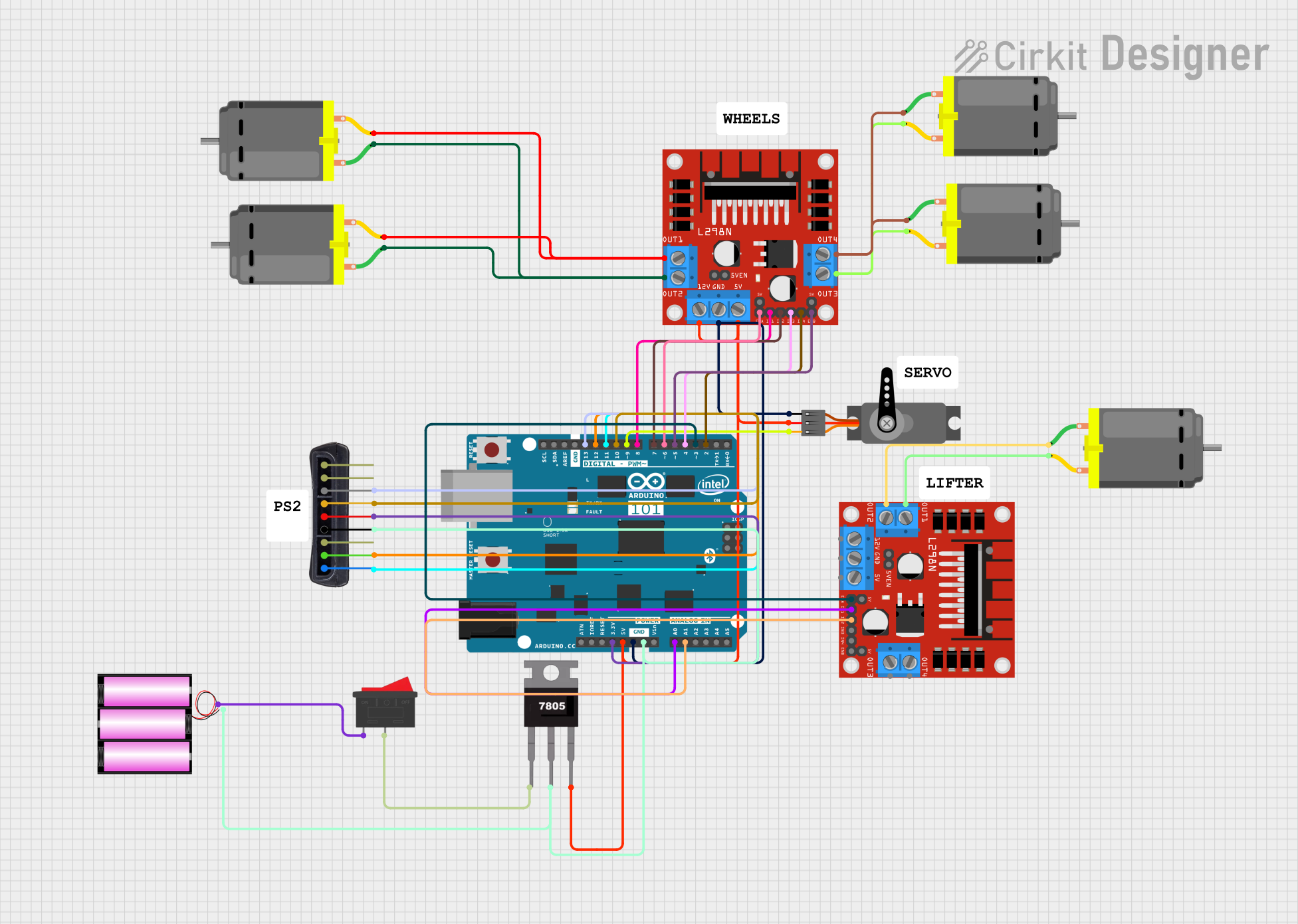
Circuit Documentation
Summary
This circuit involves an Arduino 101 microcontroller interfacing with various components including a PS2 controller, a servo motor, multiple DC motors, and L298N DC motor drivers. The circuit is powered by a 12V battery and includes a 7805 voltage regulator to provide a stable 5V supply. A rocker switch is used to control the power supply.
Component List
DC Motor
- Pins: pin 1, pin 2
- Description: A standard DC motor used for various mechanical movements.
Servo
- Pins: GND, VCC, PWM
- Description: A servo motor used for precise control of angular position.
Arduino 101
- Pins: A5/SCL, A4/SDA, AREF, GND, D13/SCK, D12/MISO, D11 PWM/MOSI, D10 PWM/SS, D9 PWM, D8, D7, D6 PWM, D5 PWM, D4, D3 PWM, D2, D1/TX, D0/RX, AIN, ioref, RESET, 3V3, 5V, VIN, A0, A1, A2, A3, ICSP MISO, ICSP SCK, ICSP MOSI
- Description: A microcontroller board based on the Intel Curie module.
L298N DC Motor Driver
- Pins: OUT1, OUT2, 12V, GND, 5V, OUT3, OUT4, 5V-ENA-JMP-I, 5V-ENA-JMP-O, +5V-J1, +5V-J2, ENA, IN1, IN2, IN3, IN4, ENB
- Description: A dual H-bridge motor driver used to control the speed and direction of DC motors.
PS2 Controller
- Pins: DATA, CMD, GND, VCC, Att, CLK
- Description: A PlayStation 2 controller used for user input.
Battery 12V
- Pins: +, -
- Description: A 12V battery used to power the circuit.
Rocker Switch
- Pins: 1, 2
- Description: A switch used to control the power supply to the circuit.
7805 Voltage Regulator
- Pins: Vin, Gnd, Vout
- Description: A voltage regulator used to provide a stable 5V output from a higher voltage input.
Wiring Details
DC Motor
Motor 1
- pin 1 connected to pin 1 of another DC Motor and OUT2 of L298N DC motor driver
- pin 2 connected to pin 2 of another DC Motor and OUT1 of L298N DC motor driver
Motor 2
- pin 1 connected to pin 1 of another DC Motor and OUT2 of L298N DC motor driver
- pin 2 connected to pin 2 of another DC Motor and OUT1 of L298N DC motor driver
Motor 3
- pin 1 connected to OUT4 of L298N DC motor driver
- pin 2 connected to OUT3 of L298N DC motor driver
Motor 4
- pin 1 connected to OUT4 of L298N DC motor driver
- pin 2 connected to OUT3 of L298N DC motor driver
Motor 5
- pin 1 connected to OUT2 of L298N DC motor driver
- pin 2 connected to OUT1 of L298N DC motor driver
Servo
- Servo Motor
- PWM connected to D9 PWM of Arduino 101
- VCC connected to Vout of 7805 voltage regulator
- GND connected to GND of Arduino 101
Arduino 101
- Microcontroller
- D13/SCK connected to CLK of PS2 controller
- D12/MISO connected to CMD of PS2 controller
- D11 PWM/MOSI connected to DATA of PS2 controller
- D10 PWM/SS connected to Att of PS2 controller
- D9 PWM connected to PWM of Servo
- D8 connected to IN1 of L298N DC motor driver
- D7 connected to IN2 of L298N DC motor driver
- D6 PWM connected to ENA of L298N DC motor driver
- D5 PWM connected to ENB of L298N DC motor driver
- D4 connected to IN3 of L298N DC motor driver
- D3 PWM connected to ENA of another L298N DC motor driver
- D2 connected to IN4 of L298N DC motor driver
- 3V3 connected to VCC of PS2 controller
- 5V connected to Vout of 7805 voltage regulator
- GND connected to GND of Servo, L298N DC motor driver, and PS2 controller
- A0 connected to IN1 of another L298N DC motor driver
- A1 connected to IN2 of another L298N DC motor driver
L298N DC Motor Driver
Motor Driver 1
- IN1 connected to D8 of Arduino 101
- IN2 connected to D7 of Arduino 101
- ENA connected to D6 PWM of Arduino 101
- ENB connected to D5 PWM of Arduino 101
- IN3 connected to D4 of Arduino 101
- IN4 connected to D2 of Arduino 101
- 12V connected to Vout of 7805 voltage regulator
- 5V connected to Vout of 7805 voltage regulator
- GND connected to GND of Arduino 101
Motor Driver 2
- IN1 connected to A0 of Arduino 101
- IN2 connected to A1 of Arduino 101
- ENA connected to D3 PWM of Arduino 101
- OUT1 connected to pin 2 of a DC Motor
- OUT2 connected to pin 1 of a DC Motor
- OUT3 connected to pin 2 of another DC Motor
- OUT4 connected to pin 1 of another DC Motor
PS2 Controller
- Controller
- CLK connected to D13/SCK of Arduino 101
- CMD connected to D12/MISO of Arduino 101
- DATA connected to D11 PWM/MOSI of Arduino 101
- Att connected to D10 PWM/SS of Arduino 101
- VCC connected to 3V3 of Arduino 101
- GND connected to GND of Arduino 101
Battery 12V
- Power Supply
-
- connected to pin 1 of Rocker Switch
-
- connected to Gnd of 7805 voltage regulator and GND of Arduino 101
-
Rocker Switch
- Switch
- pin 1 connected to + of Battery 12V
- pin 2 connected to Vin of 7805 voltage regulator
7805 Voltage Regulator
- Voltage Regulator
- Vin connected to pin 2 of Rocker Switch
- Gnd connected to - of Battery 12V
- Vout connected to VCC of Servo, 5V of Arduino 101, 12V and 5V of L298N DC motor driver
Code
No code is provided for this circuit.