
Dual Arduino Pro Mini with NRF24L01 Wireless Communication and Humidity Sensing
View and Edit Project In Cirkit Designer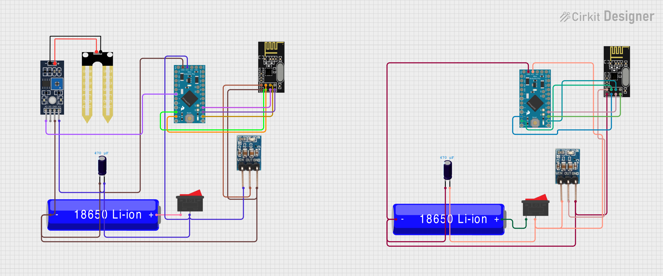
Circuit Documentation
Summary
This circuit is designed to interface an Arduino Pro Mini with an NRF24L01 wireless transceiver module, powered by a 18650 Li-ion battery. The circuit includes a 3.3V voltage regulator to ensure the NRF24L01 and the Arduino Pro Mini are supplied with the correct voltage. A humidity sensor (YL-69) is also connected to the Arduino for environmental sensing. The power supply can be controlled by a rocker switch, and electrolytic capacitors are used for voltage smoothing.
Component List
NRF24L01 Wireless Transceiver Module
- Description: A wireless transceiver module that operates at 2.4 GHz.
- Pins: IRQ (not used), MOSI, CSN, VCC (3V), GND, CE, SCK, MISO.
18650 Li-ion Battery
- Description: A rechargeable battery providing the power source for the circuit.
- Pins: -, +.
Rocker Switch
- Description: A switch to control the power supply to the circuit.
- Pins: 1, 2.
3.3V Voltage Regulator
- Description: Regulates input voltage down to a stable 3.3V output.
- Pins: GND, OUT, Vin.
Electrolytic Capacitor
- Description: Provides voltage smoothing in the power supply circuit.
- Pins: -, +.
- Properties: Capacitance: 0.00047 Farads.
Arduino Pro Mini
- Description: A compact microcontroller board based on the ATmega328.
- Pins: DTR, TXO, RXI, VCC, GND, A4, A5, RAW, RESET, A3, A2, A1, A0, SCK, MISO, MOSI, D10, D9, D8, D7, D6, D5, D4, D3, D2.
Humidity Sensor (YL-69)
- Description: A sensor for detecting humidity levels in the soil.
- Pins: A0, D0, GND, VCC.
Wiring Details
NRF24L01 Wireless Transceiver Module
- MOSI connected to Arduino Pro Mini MOSI
- CSN connected to Arduino Pro Mini D8
- VCC (3V) connected to 3.3V regulator OUT
- GND connected to system ground
- CE connected to Arduino Pro Mini D7
- SCK connected to Arduino Pro Mini SCK
- MISO connected to Arduino Pro Mini MISO
18650 Li-ion Battery
- (-) connected to system ground
- (+) connected to the input of the rocker switch
Rocker Switch
- Pin 1 connected to the positive terminal of the 18650 Li-ion Battery
- Pin 2 connected to the Vin of the 3.3V voltage regulator and the positive side of the electrolytic capacitor
3.3V Voltage Regulator
- GND connected to system ground
- OUT connected to VCC of NRF24L01 and Arduino Pro Mini
- Vin connected to the output of the rocker switch and the positive side of the electrolytic capacitor
Electrolytic Capacitor
- (-) connected to system ground
- (+) connected to the output of the rocker switch and the Vin of the 3.3V voltage regulator
Arduino Pro Mini
- VCC connected to 3.3V regulator OUT
- GND connected to system ground
- SCK connected to NRF24L01 SCK
- MISO connected to NRF24L01 MISO
- MOSI connected to NRF24L01 MOSI
- D8 connected to NRF24L01 CSN
- D7 connected to NRF24L01 CE
- D3 connected to Humidity Sensor YL-69 A0
Humidity Sensor (YL-69)
- A0 connected to Arduino Pro Mini D3
- VCC connected to 3.3V regulator OUT
- GND connected to system ground
Documented Code
Arduino Pro Mini (Instance 1)
File: sketch.ino
void setup() {
  // put your setup code here, to run once:

}

void loop() {
  // put your main code here, to run repeatedly:

}
Arduino Pro Mini (Instance 2)
File: sketch.ino
void setup() {
  // put your setup code here, to run once:

}

void loop() {
  // put your main code here, to run repeatedly:

}
Note: The provided code for both instances of the Arduino Pro Mini is a template and does not include specific functionality. It is expected that the user will add the necessary code to interact with the NRF24L01 module and the Humidity Sensor YL-69.