
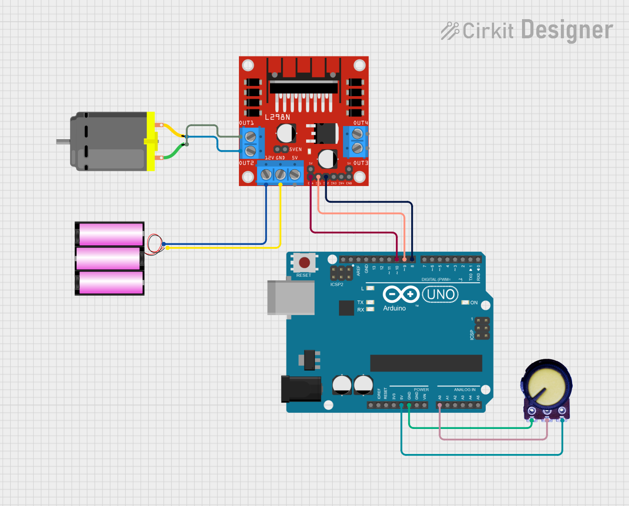
Circuit Documentation
Summary
This circuit is designed to control a DC motor using an Arduino UNO microcontroller and an L298N DC motor driver. The motor's speed is regulated by a potentiometer, which provides analog input to the Arduino. The Arduino processes this input and sends PWM signals to the L298N driver to control the motor speed. The motor driver is powered by a 12V battery, which also supplies the motor.
Component List
Arduino UNO
- Microcontroller board based on the ATmega328P
- It has 14 digital input/output pins, 6 analog inputs, a 16 MHz quartz crystal, a USB connection, a power jack, an ICSP header, and a reset button.
L298N DC Motor Driver
- A module that can control up to two DC motors by providing bidirectional drive currents.
- It has an onboard 5V regulator which can be enabled by a jumper.
12V Battery
- Provides the power source for the motor and motor driver module.
DC Motor
- A simple electric motor that converts electrical energy into mechanical energy.
Potentiometer
- A three-terminal resistor with a sliding or rotating contact that forms an adjustable voltage divider.
Wiring Details
Arduino UNO
- 5V pin is connected to the VCC of the Potentiometer.
- GND pin is connected to the GND of the Potentiometer.
- A0 pin is connected to the Output of the Potentiometer.
- D10 pin is connected to the ENA pin of the L298N DC motor driver.
- D9 pin is connected to the IN1 pin of the L298N DC motor driver.
- D8 pin is connected to the IN2 pin of the L298N DC motor driver.
L298N DC Motor Driver
- OUT1 pin is connected to pin 1 of the DC Motor.
- OUT2 pin is connected to pin 2 of the DC Motor.
- 12V pin is connected to the + pin of the 12V Battery.
- GND pin is connected to the - pin of the 12V Battery.
DC Motor
- Pin 1 is connected to OUT1 of the L298N DC motor driver.
- Pin 2 is connected to OUT2 of the L298N DC motor driver.
Potentiometer
- VCC pin is connected to the 5V of the Arduino UNO.
- GND pin is connected to the GND of the Arduino UNO.
- Output pin is connected to A0 of the Arduino UNO.
Documented Code
#define In1 9
#define In2 8
#define speedpin 10
#define an A0
float speed;

void setup() {
  pinMode(In1, OUTPUT);
  pinMode(In2, OUTPUT);
  pinMode(speedpin, OUTPUT);
}

void loop() {
  digitalWrite(In1, LOW);
  digitalWrite(In2, HIGH);
  speed = analogRead(an);
  speed = speed * (255.0 / 1023.0);
  analogWrite(speedpin, speed);
}
Code Explanation
In1,In2, andspeedpinare defined as pin numbers 9, 8, and 10 respectively, which correspond to the control pins for the L298N motor driver.anis defined as the analog input pin A0, which is connected to the potentiometer.- In the
setup()function, the pins are configured as outputs. - The
loop()function reads the analog value from the potentiometer, scales it to a range of 0-255, and writes this value as a PWM signal tospeedpinto control the motor speed. - The motor direction is set to one direction by setting
In1to LOW andIn2to HIGH.