
Arduino-Controlled Tribometer with Load Cell Feedback and Motorized Rotary Encoder
View and Edit Project In Cirkit Designer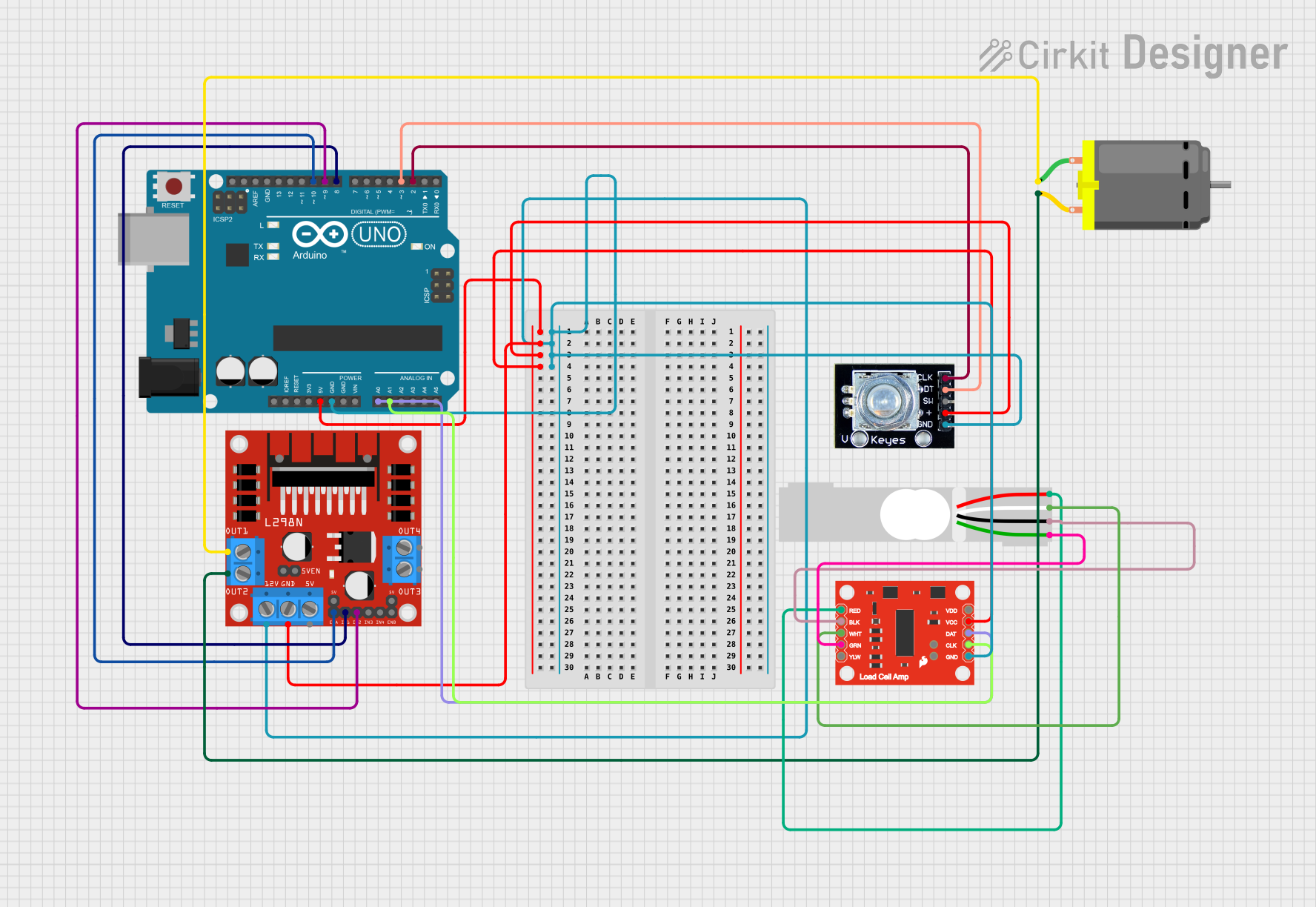
Circuit Documentation
Summary
This circuit is designed to control a DC motor using an Arduino UNO microcontroller and an L298N DC motor driver. It also includes a rotary encoder for position feedback and a load cell with an HX711 amplifier for force measurement. The Arduino UNO reads the encoder and load cell data to monitor the position and force applied to the motor. The motor's speed and direction are controlled by the Arduino through the L298N driver.
Component List
Arduino UNO
- Microcontroller board based on the ATmega328P
- It has 14 digital input/output pins, 6 analog inputs, a 16 MHz quartz crystal, a USB connection, a power jack, an ICSP header, and a reset button.
L298N DC Motor Driver
- A high-power motor driver capable of driving up to two DC motors.
- It has inputs for motor control signals and power supply connections for the motors.
DC Motor
- An electric motor that converts electrical energy into mechanical energy.
- It has two pins for power supply connection.
Rotary Encoder
- An electromechanical device that converts the angular position or motion of a shaft or axle to an analog or digital signal.
- It has five pins including signal outputs and power supply connections.
Load Cell - Red/white/black/green
- A transducer that is used to create an electrical signal whose magnitude is directly proportional to the force being measured.
- It has four pins for electrical connections.
SparkFun Load Cell Amplifier - HX711
- A precision 24-bit analog-to-digital converter (ADC) designed for weigh scales and industrial control applications to interface directly with a bridge sensor.
- It has multiple pins for power supply, analog input from the load cell, and digital output to the microcontroller.
Wiring Details
Arduino UNO
5VandGNDare used to power the circuit.A0is connected to the HX711'sDATpin.A1is connected to the HX711'sSCKpin.D10controls the motor driver'sENApin.D9is connected to the motor driver'sIN2pin.D8is connected to the motor driver'sIN1pin.D3is connected to the rotary encoder'sdtpin.D2is connected to the rotary encoder'sclkpin.
L298N DC Motor Driver
GNDand12Vare connected to the common ground and power supply respectively.ENAis controlled by Arduino'sD10.IN1andIN2are controlled by Arduino'sD8andD9respectively.OUT1andOUT2are connected to the DC motor.
DC Motor
pin 1is connected to the motor driver'sOUT1.pin 2is connected to the motor driver'sOUT2.
Rotary Encoder
+andgndare connected to the power supply and ground.dtandclkare connected to Arduino'sD3andD2respectively.
Load Cell - Red/white/black/green
E+andE-are connected to the HX711'sAVDDandGNDrespectively.A-andA+are connected to the HX711'sA-andA+respectively.
SparkFun Load Cell Amplifier - HX711
VCCandGNDare connected to the power supply and ground.DATandSCKare connected to Arduino'sA0andA1respectively.A+,A-,AVDD, andGNDare connected to the load cell.
Documented Code
#include "HX711.h"

// Define motor control pins
#define motorIn1 8
#define motorIn2 9
#define motorEN 10

// Define encoder pins
#define encoderA 2
#define encoderB 3

// HX711 Pins
#define HX711_DOUT A0
#define HX711_SCK A1

HX711 scale;

long position = 0;
float force = 0;
int lastStateA = LOW;  // To track encoder state

void setup() {
  // Motor pins
  pinMode(motorIn1, OUTPUT);
  pinMode(motorIn2, OUTPUT);
  pinMode(motorEN, OUTPUT);

  // Encoder pins
  pinMode(encoderA, INPUT);
  pinMode(encoderB, INPUT);

  // Initialize serial communication for debugging
  Serial.begin(9600);

  // Initialize HX711 scale
  scale.begin(HX711_DOUT, HX711_SCK);
  scale.set_scale();  // Calibration needed here (You can add a known weight for calibration)
  scale.tare();  // Set scale to zero

  // Print initial message
  Serial.println("Pin-on-Disk Tribometer Initialized");

  // Get a baseline (zero) for the load cell
  long zero_factor = scale.read_average();  // You can store this value for tare later if needed
}

void loop() {
  // Motor Control: Move disk
  digitalWrite(motorIn1, HIGH);  // Set motor direction
  digitalWrite(motorIn2, LOW);
  analogWrite(motorEN, 200);     // Set motor speed (PWM value from 0-255)

  // Read Encoder Values
  int stateA = digitalRead(encoderA);  // Read the state of the encoder's channel A
  int stateB = digitalRead(encoderB);  // Read the state of the encoder's channel B

  // Detect direction of rotation using both channels
  if (stateA != lastStateA) {
    if (stateB != stateA) {
      position++;  // Forward rotation
    } else {
      position--;  // Reverse rotation
    }
  }
  lastStateA = stateA;  // Update the last known state of encoderA

  // Read Load Cell (Force Measurement)
  if (scale.is_ready()) {
    force = scale.get_units();  // Get the calibrated weight or force value
    Serial.print("Force (in units): ");
    Serial.println(force);  // Print force data to the Serial Monitor
  } else {
    Serial.println("HX711 not ready");  // Error message if HX711 is not responding
  }

  // Print Encoder Position (Rotation data)
  Serial.print("Encoder Position: ");
  Serial.println(position);

  delay(100);  // Small delay to allow easier reading of values
}
This code is designed to run on the Arduino UNO microcontroller. It initializes the motor control pins, encoder pins, and the HX711 load cell amplifier. In the loop function, it controls the motor, reads the encoder position, measures the force using the load cell, and outputs the data to the serial monitor. Calibration of the HX711 is required for accurate force measurements.