Cirkit Designer
Your all-in-one circuit design IDE
Home /
Project Documentation
Arduino UNO-Based Runway Clearance and Emergency Alert System with Ultrasonic Sensor and LEDs
Circuit Documentation
Summary
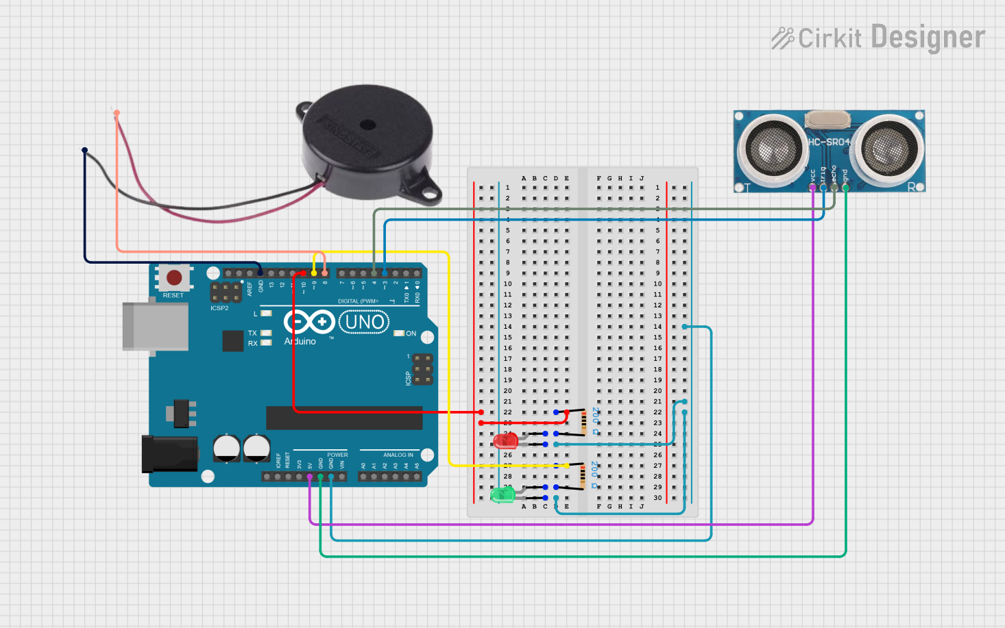
This circuit is designed to manage runway clearance and emergency alerts using an Arduino UNO. It includes LEDs to indicate runway status, a buzzer for emergency alerts, and an ultrasonic sensor for additional functionality. The system also includes resistors to limit current to the LEDs and a button to request runway clearance.
Component List
LED: Two Pin (red)
- Description: Red LED
- Pins: Cathode, Anode
LED: Two Pin (green)
- Description: Green LED
- Pins: Cathode, Anode
Resistor (200 Ohms)
- Description: Current limiting resistor
- Pins: Pin1, Pin2
Arduino UNO
- Description: Microcontroller
- Pins: UNUSED, IOREF, Reset, 3.3V, 5V, GND, Vin, A0, A1, A2, A3, A4, A5, SCL, SDA, AREF, D13, D12, D11, D10, D9, D8, D7, D6, D5, D4, D3, D2, D1, D0
Resistor (200 Ohms)
- Description: Current limiting resistor
- Pins: Pin1, Pin2
Buzzer
- Description: Sound alert
- Pins: Positive, Negative
Ultrasonic Sensor
- Description: Distance measurement sensor
- Pins: +VCC, Trigger, Echo, GND
Wiring Details
LED: Two Pin (red)
- Cathode: Connected to GND of Arduino UNO
- Anode: Connected to Pin2 of Resistor (200 Ohms)
LED: Two Pin (green)
- Cathode: Connected to GND of Arduino UNO
- Anode: Connected to Pin2 of Resistor (200 Ohms)
Resistor (200 Ohms)
- Pin1: Connected to D10 of Arduino UNO
- Pin2: Connected to Anode of Red LED
Arduino UNO
- D10: Connected to Pin1 of Resistor (200 Ohms)
- GND: Connected to Cathode of Red LED, Cathode of Green LED, GND of Ultrasonic Sensor, Negative of Buzzer
- D9: Connected to Pin1 of Resistor (200 Ohms)
- 5V: Connected to +VCC of Ultrasonic Sensor
- D8: Connected to Positive of Buzzer
- D4: Connected to Echo of Ultrasonic Sensor
- D3: Connected to Trigger of Ultrasonic Sensor
Resistor (200 Ohms)
- Pin1: Connected to D9 of Arduino UNO
- Pin2: Connected to Anode of Green LED
Buzzer
- Positive: Connected to D8 of Arduino UNO
- Negative: Connected to GND of Arduino UNO
Ultrasonic Sensor
- +VCC: Connected to 5V of Arduino UNO
- Trigger: Connected to D3 of Arduino UNO
- Echo: Connected to D4 of Arduino UNO
- GND: Connected to GND of Arduino UNO
Code Documentation
// Pin definitions
const int greenLED = 9;        // Runway clear LED
const int redLED = 10;         // Emergency LED
const int requestButton = 2;   // Button to request clearance
const int buzzer = 8;          // Buzzer for emergency alert

// Variables to keep track of states
bool runwayClear = true;       // Indicates if runway is available
bool emergencyActive = false;  // Indicates an emergency
unsigned long lastEmergencyTime = 0; // Last time an emergency occurred
unsigned long nextEmergencyDelay = 20000; // Minimum 20 seconds

void setup() {
  // Set up pin modes
  pinMode(greenLED, OUTPUT);
  pinMode(redLED, OUTPUT);
  pinMode(buzzer, OUTPUT);
  pinMode(requestButton, INPUT_PULLUP); // Using INPUT_PULLUP for stable button reading

  // Initial conditions - all indicators off
  digitalWrite(greenLED, LOW);  // Green LED off
  digitalWrite(redLED, LOW);    // Red LED off
  digitalWrite(buzzer, LOW);    // Buzzer off

  Serial.begin(9600);           // Begin serial communication for debugging

  // Seed the random number generator
  randomSeed(analogRead(A0));

  // Schedule the first random emergency
  scheduleNextEmergency();
}

void loop() {
  // Check button press
  if (digitalRead(requestButton) == LOW) {
    delay(5); // Debounce delay
    if (digitalRead(requestButton) == LOW) { // Confirm button press
      handleRunwayRequest();
    }
  }

  // Handle emergency timing
  if (millis() - lastEmergencyTime > nextEmergencyDelay) {
    activateEmergency();
    scheduleNextEmergency();
  }
}

// Function to handle runway clearance requests
void handleRunwayRequest() {
  if (!emergencyActive && runwayClear) {
    Serial.println("Clearance Granted: Aircraft may proceed.");
    digitalWrite(greenLED, HIGH); // Green LED on to signal clearance
    delay(3000);                  // Simulate runway usage (aircraft taking off/landing)
    resetRunway();                // Reset runway to clear state
  } else if (emergencyActive) {
    Serial.println("Emergency Override: Runway unavailable.");
  } else {
    Serial.println("Runway Occupied: Please wait.");
  }
}

// Function to reset the runway
void resetRunway() {
  runwayClear = true;
  digitalWrite(greenLED, LOW);  // Turn off green LED (runway is no longer cleared)
  Serial.println("Runway is now clear.");
}

// Function to activate emergency mode
void activateEmergency() {
  emergencyActive = true;
  digitalWrite(redLED, HIGH);   // Turn on red LED
  digitalWrite(buzzer, HIGH);   // Sound the buzzer
  Serial.println("Emergency Activated: Priority landing.");

  // Simulate emergency duration
  delay(2000);

  deactivateEmergency();
}

// Function to deactivate emergency mode
void deactivateEmergency() {
  emergencyActive = false;
  digitalWrite(redLED, LOW);    // Turn off red LED
  digitalWrite(buzzer, LOW);    // Turn off buzzer
  Serial.println("Emergency Cleared: Resuming normal operations.");
}

// Function to schedule the next random emergency
void scheduleNextEmergency() {
  lastEmergencyTime = millis();
  nextEmergencyDelay = 20000 + random(0, 10001);
  Serial.print("Next emergency in ");
  Serial.print(nextEmergencyDelay / 1000);
  Serial.println(" seconds.");
}
This code manages the runway clearance and emergency alerts. It uses the Arduino UNO to control LEDs, a buzzer, and an ultrasonic sensor. The code includes functions to handle runway requests, activate and deactivate emergencies, and schedule random emergencies.