
Solar-Powered Environmental Monitoring System with ESP32-C3 and Battery Management
View and Edit Project In Cirkit Designer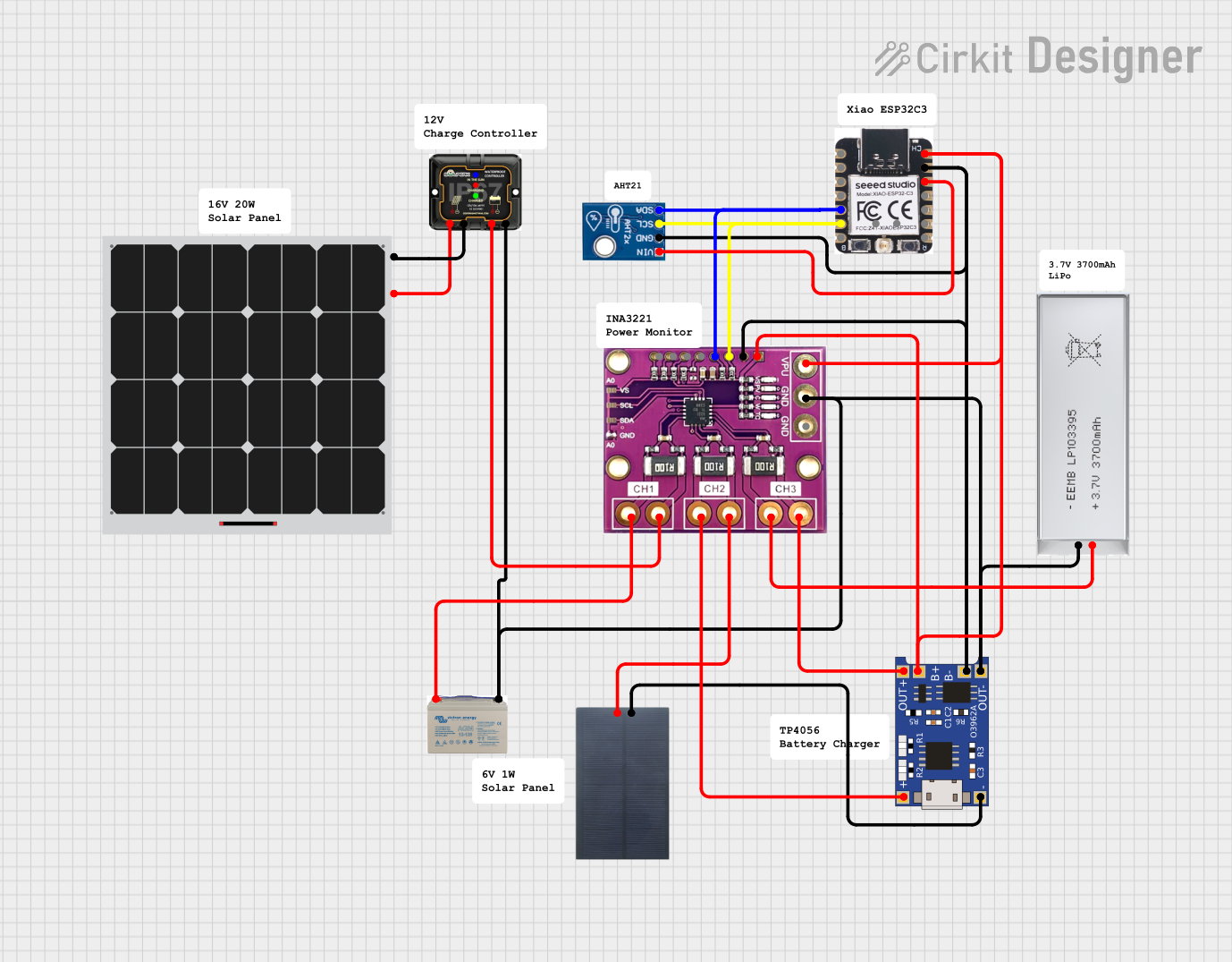
Solar-Powered Monitoring System Circuit Documentation
Summary
This circuit is designed to create a solar-powered monitoring system that utilizes a solar panel to charge a battery through an MPPT charge controller. The system includes a microcontroller for data processing and communication, a battery charging module, and sensors for environmental monitoring. The circuit is capable of monitoring its power sources and consumption through a current sensing module.
Component List
Solar Panels
- 6V 1W Solar Panel: A small solar panel used for charging the battery.
- Solar Panel: A generic solar panel, presumably with a higher power rating for charging the battery.
Batteries
- 3.7V 3700mAh Battery: A lithium-ion battery for energy storage.
- 12V AGM Battery: A lead-acid battery, typically used for higher power applications.
Charge Controllers and Modules
- MPPT 12V Charge Controller: A Maximum Power Point Tracking charge controller for optimizing the solar panel output and charging the 12V battery.
- TP4056: A lithium-ion battery charging module with protection, used for charging the 3.7V battery from the 6V solar panel.
Sensors and Monitoring
- AHT21: A digital temperature and humidity sensor for environmental monitoring.
- INA3221-Updated-3_Ind_Loads: A triple-channel shunt and bus voltage monitor with I2C interface, used for current sensing and voltage monitoring.
Microcontroller
- Xiao esp32c3-front: A compact microcontroller with Wi-Fi capabilities, used for data processing and communication.
Comments
- Comment: Placeholder components that may represent annotations or notes within the circuit design.
Wiring Details
6V 1W Solar Panel
- + connected to TP4056 IN+
- - connected to TP4056 IN-
Solar Panel
- + connected to MPPT 12V Charge Controller +
- - connected to MPPT 12V Charge Controller -
3.7V 3700mAh Battery
- + connected to TP4056 OUT+ and INA3221 VIN3-
- - connected to TP4056 OUT-
12V AGM Battery
- + connected to INA3221 VIN1-
- - connected to MPPT 12V Charge Controller -
MPPT 12V Charge Controller
- + connected to Solar Panel + and INA3221 VIN1+
- - connected to Solar Panel - and various GND connections
TP4056
- B- connected to GND
- B+ connected to VPU, VS, and VUSB/5V
- OUT- connected to 3.7V Battery -, GND, 12V Battery -, and MPPT 12V Charge Controller -
- OUT+ connected to INA3221 VIN3+
- IN- connected to 6V Solar Panel -
- IN+ connected to INA3221 VIN2-
AHT21
- Vin+ connected to 3V3
- GND connected to GND
- SCL connected to SCL
- SDA connected to SDA
INA3221-Updated-3_Ind_Loads
- VIN1- connected to 12V Battery +
- VIN1+ connected to MPPT 12V Charge Controller +
- VIN2- connected to TP4056 IN+
- VIN2+ connected to 6V Solar Panel +
- VIN3- connected to 3.7V Battery +
- VIN3+ connected to TP4056 OUT+
- VPU connected to B+
- GND connected to GND
- VS connected to B+
- SCL connected to SCL
- SDA connected to SDA
- PV, CRI, WAR, TC are not connected in the provided net list.
Xiao esp32c3-front
- 3V3 connected to AHT21 Vin+
- GND connected to GND
- GPIO6/SDA/D4 connected to SDA
- GPIO7/SCL/D5 connected to SCL
- VUSB/5V connected to B+
- Other pins are not connected in the provided net list.
Documented Code
No code has been provided for the microcontroller. The system's functionality in terms of data processing, control, and communication would be implemented here. The code would typically initialize the I2C communication, read sensor data from the AHT21 and INA3221, manage power through the MPPT and TP4056, and handle any communication protocols for data transmission.