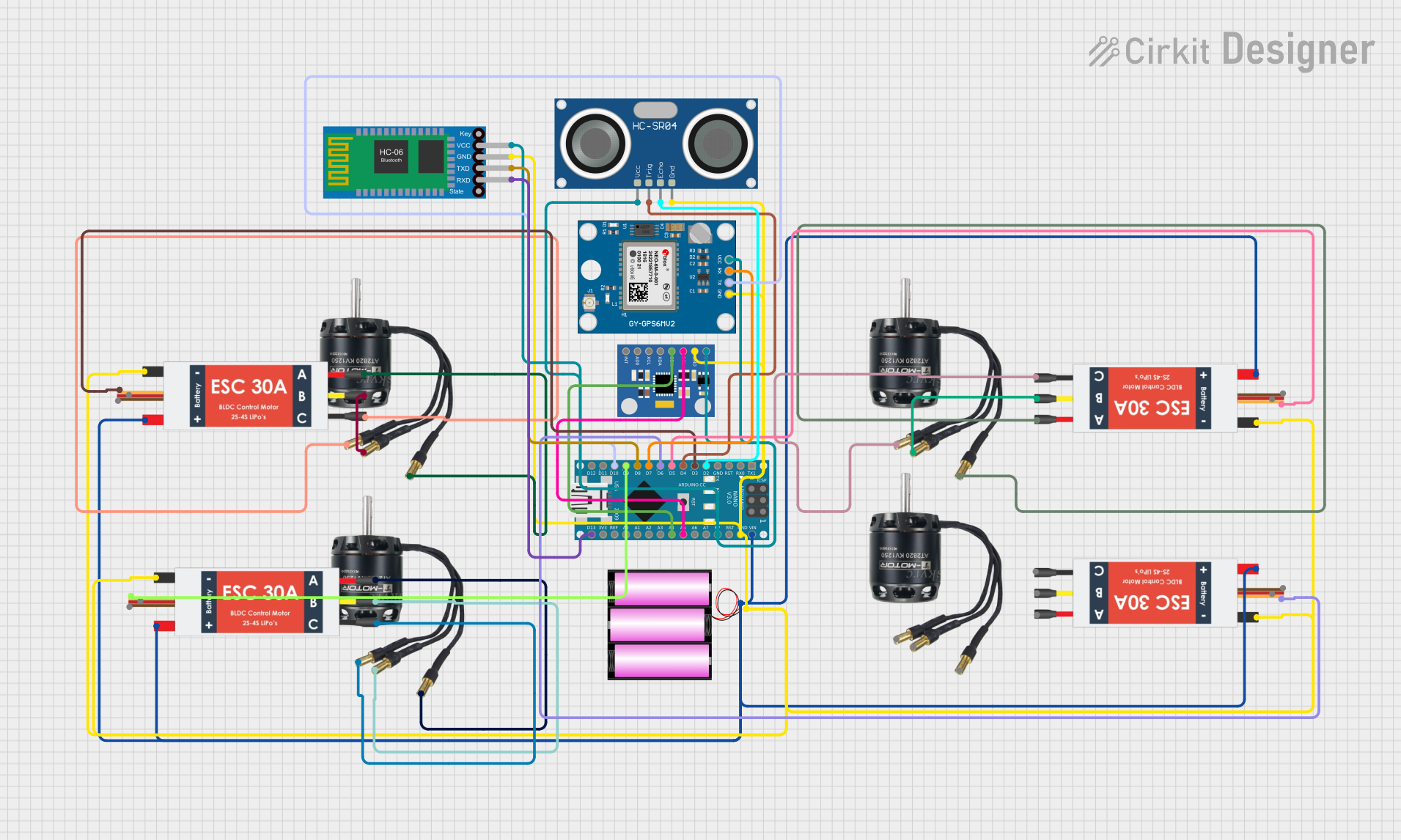
Quadcopter Flight Controller with GPS and Bluetooth Telemetry

Circuit Documentation
Summary
This circuit is designed to control multiple Brushless DC (BLDC) motors using Electronic Speed Controllers (ESCs), interfaced with an Arduino Nano microcontroller. The circuit includes a 12V battery as the power source, sensors like the MPU6050 accelerometer/gyroscope and HC-SR04 ultrasonic sensor for input, and a Neo 6M GPS module and Bluetooth HC-06 for communication. The Arduino Nano serves as the central processing unit, reading sensor data, controlling the ESCs, and communicating with external devices.
Component List
Power Source
- Battery 12V: Provides the main power supply to the circuit.
Actuators
- BLDC Motors: Four motors that convert electrical energy into mechanical rotation.
Control
- Electronic Speed Controllers (ESC): Four controllers that regulate the power supplied to the BLDC motors.
Microcontroller
- Arduino Nano: The brain of the circuit, it processes inputs and outputs signals to control the ESCs.
Sensors
- MPU6050 Accelerometer + Gyroscope: Measures acceleration and rotational rates.
- HC-SR04 Ultrasonic Sensor: Measures distance by emitting ultrasonic waves.
- Neo 6M GPS Module: Provides location data.
Communication
- Bluetooth HC-06: Allows wireless communication with other devices.
Wiring Details
Power Source
- Battery 12V
+to ESCs Battery VCC and Arduino Nano VIN-to ESCs Battery GND, Arduino Nano GND, and all GND pins of sensors and modules
Actuators
- BLDC Motors
Wire A,Wire B,Wire Cto corresponding M1, M2, M3 pins on each ESC
Control
- Electronic Speed Controllers (ESC)
Battery VCCto Battery+Battery GNDto Battery-Signalto Arduino Nano digital pins (D3, D5, D6, D9)5v outandGND outnot connectedM1,M2,M3to corresponding wires of BLDC Motors
Microcontroller
- Arduino Nano
VINto Battery+GNDto Battery-- Digital pins (D2, D3, D4, D5, D6, D7, D8, D9, D10, D13/SCK) to various signal pins on ESCs, sensors, and modules
5Vto VCC pins of sensors and modulesA4,A5to SDA and SCL pins of MPU6050AREF,3V3, and other analog pins not connected
Sensors
MPU6050 Accelerometer + Gyroscope
VCCto Arduino Nano5VGNDto Arduino NanoGNDSDAto Arduino NanoA4SCLto Arduino NanoA5- Other pins not connected
HC-SR04 Ultrasonic Sensor
VCCto Arduino Nano5VGNDto Arduino NanoGNDTRIGto Arduino NanoD4ECHOto Arduino NanoD2
Neo 6M GPS Module
VCCto Arduino Nano5VGNDto Arduino NanoGNDTXto Arduino NanoD10RXto Arduino NanoD7
Communication
- Bluetooth HC-06
VCCto Arduino Nano5VGNDto Arduino NanoGNDTXDto Arduino NanoD8RXDto Arduino NanoD13/SCK
Documented Code
Arduino Nano Code (sketch.ino)
void setup() {
  // put your setup code here, to run once:

}

void loop() {
  // put your main code here, to run repeatedly:

}
Note: The provided code is a template and does not contain any functional code. It needs to be populated with the logic for reading sensors, controlling the ESCs, and handling communication.
Additional Documentation (documentation.txt)
No additional documentation code was provided.