ESP8266 NodeMCU Based Energy Monitoring Display with PZEM004T and OLED Screen
Circuit Documentation
Summary
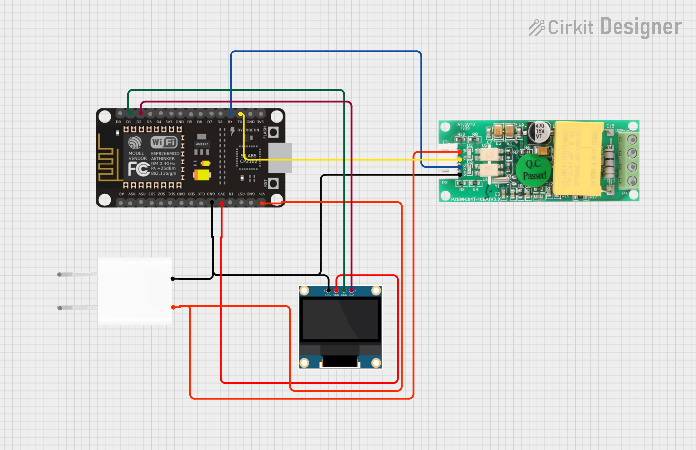
The circuit in question is designed to interface an ESP8266 NodeMCU microcontroller with a PZEM004T power monitoring module and a 0.96" OLED display. The ESP8266 NodeMCU serves as the central processing unit, collecting data from the PZEM004T and displaying relevant information on the OLED. The circuit is powered by a 5V adapter, which provides the necessary voltage to the components. Communication between the ESP8266 and the OLED is established via I2C protocol, while the ESP8266 communicates with the PZEM004T using UART (serial communication).
Component List
ESP8266 NodeMCU
- Description: A microcontroller module with Wi-Fi capabilities, based on the ESP8266 chipset.
- Pins: D0, D1, D2, D3, D4, 3V3, GND, D5, D6, D7, D8, RX, TX, A0, RSV, SD3, SD2, SD1, CMD, SD0, CLK, EN, RST, VIN
PZEM004T
- Description: A power monitoring module capable of measuring voltage, current, power, and energy in an electrical circuit.
- Pins: VCC, RX, TX, GND, IN, OUT
0.96" OLED
- Description: A small OLED display for visual output, typically used for displaying text and simple graphics.
- Pins: GND, VDD, SCK, SDA
5V Adapter
- Description: A power supply module that converts AC input to a 5V DC output.
- Pins: AC In 1, AC In 2, 5V, GND
Wiring Details
ESP8266 NodeMCU
- D1 connected to OLED SCK (Serial Clock for I2C)
- D2 connected to OLED SDA (Serial Data for I2C)
- RX connected to PZEM004T TX (UART communication)
- TX connected to PZEM004T RX (UART communication)
- GND connected to OLED GND, PZEM004T GND, and 5V Adapter GND (Common ground)
- 3V3 connected to OLED VDD (Power supply for OLED)
- VIN connected to PZEM004T VCC and 5V Adapter 5V (Power supply for PZEM004T)
PZEM004T
- VCC connected to ESP8266 NodeMCU VIN and 5V Adapter 5V
- RX connected to ESP8266 NodeMCU TX
- TX connected to ESP8266 NodeMCU RX
- GND connected to ESP8266 NodeMCU GND and 5V Adapter GND
0.96" OLED
- GND connected to ESP8266 NodeMCU GND and 5V Adapter GND
- VDD connected to ESP8266 NodeMCU 3V3
- SCK connected to ESP8266 NodeMCU D1
- SDA connected to ESP8266 NodeMCU D2
5V Adapter
- 5V connected to ESP8266 NodeMCU VIN and PZEM004T VCC
- GND connected to ESP8266 NodeMCU GND, OLED GND, and PZEM004T GND
Documented Code
No code has been provided for the microcontrollers in the circuit. The code would typically include initialization and configuration of the I2C and UART interfaces, as well as the main logic for data acquisition from the PZEM004T and display routines for the OLED. Since the code is not available, this section cannot be completed at this time.