
Arduino Mega 2560 Controlled Vending Machine with Multi-Motor Interface and Coin Acceptance
View and Edit Project In Cirkit Designer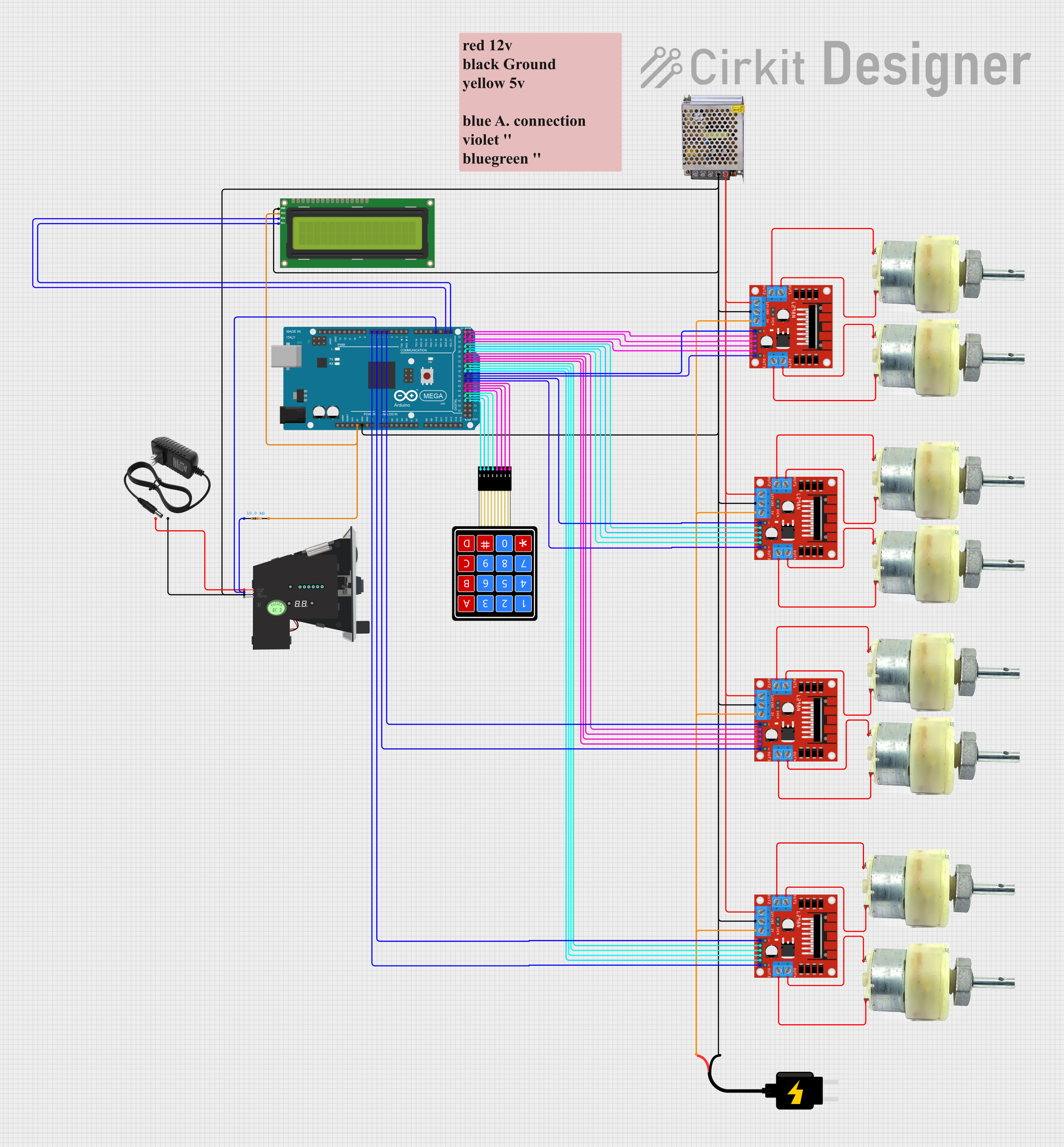
Circuit Documentation
Summary
This circuit is designed to control multiple DC motors using L298N motor drivers, interfaced with an Arduino Mega 2560 microcontroller. The system includes an I2C LCD screen for user feedback, a 4x4 membrane matrix keypad for user input, and a multi-coin acceptor for monetary input. The circuit is powered by a 12V 5A power supply, with a separate 5V DC source for logic level components. The Arduino Mega 2560 is programmed to manage the operation of the motors based on the user input and coin validation.
Component List
Microcontroller
- Arduino Mega 2560: A microcontroller board based on the ATmega2560, with numerous digital and analog I/O pins.
Motor Drivers
- L298N DC Motor Drivers: Modules used to control the direction and speed of DC motors.
Display
- I2C LCD 16x2 Screen: A 16x2 character LCD display that uses the I2C communication protocol.
Input Devices
- 4X4 Membrane Matrix Keypad: A 16-button keypad for user input.
- Multi Coin Acceptor: A device that validates coins and outputs corresponding signals.
Motors
- 12V Geared Motors: DC motors with gear reduction for increased torque.
Power Supply
- POWER SUPPLY 12V 5AMP: Provides the main power for the motors and motor drivers.
- 12v power supply: Supplies power to the coin acceptor.
- DC Source 5V: Provides 5V power for logic level components.
Miscellaneous
- Resistor: A 10k Ohm resistor used for pull-up on the coin acceptor signal line.
Wiring Details
Arduino Mega 2560
5Vconnected to the VCC of the I2C LCD screen and a 10k Ohm resistor.GNDconnected to the common ground rail.D21/SCLconnected to the SCL pin of the I2C LCD screen.D20/SDAconnected to the SDA pin of the I2C LCD screen.D18/TX1connected to the COIN pin of the Multi Coin Acceptor through a 10k Ohm resistor.D4 PWM-D7 PWMconnected to the ENA and ENB pins of the L298N motor drivers.D22-D37connected to the IN1 - IN4 pins of the L298N motor drivers for motor control.D42-D49connected to the 4x4 Membrane Matrix Keypad.
L298N DC Motor Drivers
GNDconnected to the common ground rail.12Vconnected to the 12V output of the 12V 5A power supply.5Vconnected to the 5V DC source.ENAandENBconnected to the corresponding PWM pins on the Arduino Mega 2560 for motor speed control.IN1-IN4connected to the corresponding digital pins on the Arduino Mega 2560 for motor direction control.OUT1-OUT4connected to the terminals of the 12V Geared Motors.
I2C LCD 16x2 Screen
VCC (5V)connected to the 5V output from the Arduino Mega 2560.GNDconnected to the common ground rail.SCLconnected to the D21/SCL pin on the Arduino Mega 2560.SDAconnected to the D20/SDA pin on the Arduino Mega 2560.
4X4 Membrane Matrix Keypad
R1-R4andC1-C4connected to the corresponding digital pins on the Arduino Mega 2560.
Multi Coin Acceptor
COINconnected to the D18/TX1 pin on the Arduino Mega 2560 through a 10k Ohm resistor.GNDconnected to the common ground rail.DC12Vconnected to the 12v power supply.
12V Geared Motors
Terminal 1andTerminal 2connected to the corresponding OUT pins on the L298N motor drivers.
Power Supplies
- POWER SUPPLY 12V 5AMP:
GND (DC)connected to the common ground rail,12V-24V Output (DC)connected to the 12V input on the L298N motor drivers. - 12v power supply:
+connected to the DC12V pin on the Multi Coin Acceptor,-connected to the common ground rail. - DC Source 5V:
VCCconnected to the 5V input on the L298N motor drivers,GNDconnected to the common ground rail.
Resistor
- 10k Ohm Resistor: One end connected to the 5V output from the Arduino Mega 2560, the other end connected to the COIN pin of the Multi Coin Acceptor and the D18/TX1 pin on the Arduino Mega 2560.
Documented Code
#include <Keypad.h>
#include <LiquidCrystal.h>

// Motor Driver Pins
const int motorPins[8][2] = {
  {22, 23},   // Motor 1
  {24, 25},   // Motor 2
  {26, 27},   // Motor 3
  {28, 29},   // Motor 4
  {30, 31},   // Motor 5
  {32, 33},   // Motor 6
  {34, 35},   // Motor 7
  {36, 37}    // Motor 8
};

// Enable pins for L298N Motor Drivers
const int enablePins[8] = {38, 39, 40, 41, 4, 5, 6, 7}; // ENA and ENB for each L298N driver

// Keypad Configuration
const byte ROWS = 4; // Four rows
const byte COLS = 4; // Four columns
char keys[ROWS][COLS] = {
  {'1', '2', '3', 'A'},
  {'4', '5', '6', 'B'},
  {'7', '8', '9', 'C'},
  {'*', '0', '#', 'D'}
};
byte rowPins[ROWS] = {42, 43, 44, 45}; // Connect to the row pins
byte colPins[COLS] = {46, 47, 48, 49}; // Connect to the column pins
Keypad keypad = Keypad(makeKeymap(keys), rowPins, colPins, ROWS, COLS);

// LCD Configuration
LiquidCrystal lcd(8, 9, 10, 11, 12, 13); // RS, E, D4, D5, D6, D7

// Coin Acceptor Pin
const int coinPin = 18; // Use pin with interrupt capability
volatile int credits = 0;
volatile int coinCount = 0;
volatile int coinValue = 0;
const int coinValues[] = {1, 5, 10}; // Example values for different coins

// Prices for each slot
const int slotPrices[8] = {2, 3, 1, 4, 2, 3, 5, 2}; // Prices for slots 1 to 8

// Motor Control Variables
const int motorRunTime = 3000; // Motor run time in milliseconds

// Interrupt Service Routine for Coin Acceptor
void coinISR() {
  coinCount++;
  if (coinCount == 1) {
    coinValue = coinValues[0]; // Example: 1 pulse = 1 credit
  } else if (coinCount == 2) {
    coinValue = coinValues[1]; // Example: 2 pulses = 5 credits
  } else if (coinCount == 3) {
    coinValue = coinValues[2]; // Example: 3 pulses = 10 credits
  }
  credits += coinValue;
  coinCount = 0; // Reset coin count after detecting a coin
}

void setup() {
  // Setup LCD
  lcd.begin(16, 2);
  lcd.print("Insert coin...");

  // Setup Keypad
  keypad.addEventListener(keypadEvent);

  // Setup Coin Acceptor
  pinMode(coinPin, INPUT_PULLUP);
  attachInterrupt(digitalPinToInterrupt(coinPin), coinISR, RISING);

  // Setup Motor Pins
  for (int i = 0; i < 8; i++) {
    pinMode(motorPins[i][0], OUTPUT);
    pinMode(motorPins[i][1], OUTPUT);
  }

  // Setup Enable Pins for L298N Drivers
  for (int i = 0; i < 8; i++) {
    pinMode(enablePins[i], OUTPUT);
    digitalWrite(enablePins[i], HIGH); // Enable motor drivers
  }
}

void loop() {
  // Display Credits
  lcd.setCursor(0, 0);
  lcd.print