
ESP32-Based Smart Environmental Monitoring System with Battery-Powered Heater
View and Edit Project In Cirkit Designer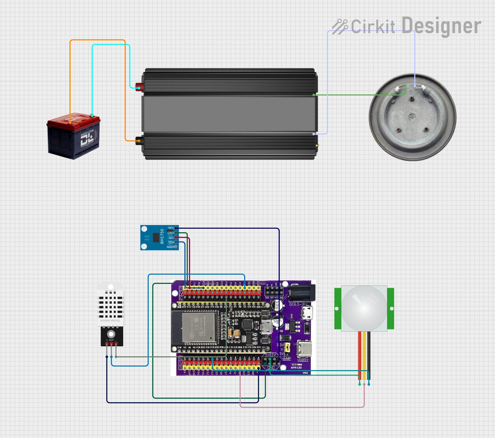
Circuit Documentation
Summary
This document provides a detailed overview of a circuit that includes various sensors, a microcontroller, a power inverter, a heater element, and a battery. The circuit is designed to interface with an ESP32 microcontroller, which reads data from the sensors and controls the heater element. The power inverter is used to convert the battery's 12V output to a suitable voltage for the heater element.
Component List
PIR Sensor
- Description: Passive Infrared Sensor
- Pins: VDD, SIG, GND
BH1750
- Description: Light Intensity Sensor
- Pins: VCC, GND, SCL, SDA, ADDR
DHT22
- Description: Temperature and Humidity Sensor
- Pins: +, Out, -
ESP32 on Baseboard
- Description: Microcontroller
- Pins: GPIO23, GPIO22, GPIO1/TX, GPIO3/RX, GPIO21, GPIO19, GPIO18, GPIO5, GPIO17, GPIO16, GPIO4, GPIO0, GPIO2, GPIO15, SD1, SD0, CLK, V, G, GPIO36, GPIO39, GPIO34, GPIO35, GPIO32, GPIO33, GPIO25, GPIO26, GPIO27, GPIO14, GPIO12, GPIO13, SD2, SD3, GND, 5V, 3V, TX, RX, VCC, D22, D21
Power Inverter
- Description: Converts 12V DC to a suitable voltage for the heater element
- Pins: -, +
Heater Element
- Description: Heating Element
- Pins: VCC, GND
Battery 12V
- Description: Power Source
- Pins: -, +
Wiring Details
PIR Sensor
- VDD connected to 5V of ESP32 on Baseboard
- SIG connected to GPIO13 of ESP32 on Baseboard
- GND connected to G of ESP32 on Baseboard
BH1750
- VCC connected to 3V of ESP32 on Baseboard
- GND connected to GND of ESP32 on Baseboard
- SCL connected to GPIO22 of ESP32 on Baseboard
- SDA connected to GPIO21 of ESP32 on Baseboard
DHT22
- + connected to 5V of ESP32 on Baseboard
- Out connected to GPIO15 of ESP32 on Baseboard
- - connected to G of ESP32 on Baseboard
Battery 12V
- - connected to - of Power Inverter
- + connected to + of Power Inverter
Power Inverter
- + connected to VCC of Heater Element
- - connected to GND of Heater Element
Documented Code
There is no code provided for the microcontrollers in this circuit.
This document provides a comprehensive overview of the circuit, including a summary, a detailed component list, wiring details, and a section for documented code. This should serve as a useful reference for understanding and replicating the circuit.