Cirkit Designer
Your all-in-one circuit design IDE
Home /
Project Documentation
L298N DC Motor Driver Controlled DC Motor System
Circuit Documentation
Summary
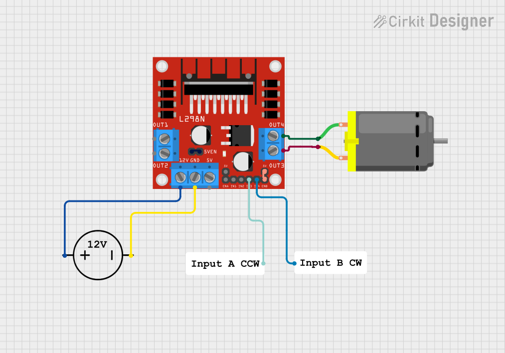
This document provides a detailed overview of a circuit designed to control a DC motor using an L298N DC motor driver. The circuit is powered by a DC power source and includes resistors for current limiting. The document includes a list of components, wiring details, and code (if any) for the microcontrollers used in the circuit.
Component List
L298N DC Motor Driver
- Pins: OUT1, OUT2, 12V, GND, 5V, OUT3, OUT4, 5V-ENA-JMP-I, 5V-ENA-JMP-O, +5V-J1, +5V-J2, ENA, IN1, IN2, IN3, IN4, ENB
- Description: A dual H-bridge motor driver that allows control of the speed and direction of two DC motors.
DC Power Source
- Pins: Ground, Positive
- Description: Provides the necessary power for the circuit.
DC Motor
- Pins: pin 1, pin 2
- Description: A motor that converts electrical energy into mechanical motion.
Resistor (200 Ohms)
- Pins: pin1, pin2
- Description: Limits the current in the circuit.
- Properties: Resistance: 200 Ohms
Resistor (200 Ohms)
- Pins: pin1, pin2
- Description: Limits the current in the circuit.
- Properties: Resistance: 200 Ohms
Wiring Details
L298N DC Motor Driver
- 12V is connected to Positive of the DC Power Source.
- GND is connected to Ground of the DC Power Source.
- OUT3 is connected to pin 2 of the DC Motor.
- OUT4 is connected to pin 1 of the DC Motor.
- 5V-ENA-JMP-I is connected to 5V-ENA-JMP-O of the same L298N DC Motor Driver.
- +5V-J2 is connected to ENB of the same L298N DC Motor Driver.
- IN3 is connected to pin2 of the Resistor (200 Ohms).
- IN4 is connected to pin1 of the Resistor (200 Ohms).
DC Power Source
- Positive is connected to 12V of the L298N DC Motor Driver.
- Ground is connected to GND of the L298N DC Motor Driver.
DC Motor
- pin 1 is connected to OUT4 of the L298N DC Motor Driver.
- pin 2 is connected to OUT3 of the L298N DC Motor Driver.
Resistor (200 Ohms)
- pin1 is connected to IN4 of the L298N DC Motor Driver.
- pin2 is connected to IN3 of the L298N DC Motor Driver.
Resistor (200 Ohms)
- pin1 is connected to IN4 of the L298N DC Motor Driver.
- pin2 is connected to IN3 of the L298N DC Motor Driver.
Code
There is no code provided for this circuit.
This document provides a comprehensive overview of the circuit, including the components used, their connections, and any associated code. This should serve as a useful reference for understanding and replicating the circuit.