
Circuit Documentation
Summary
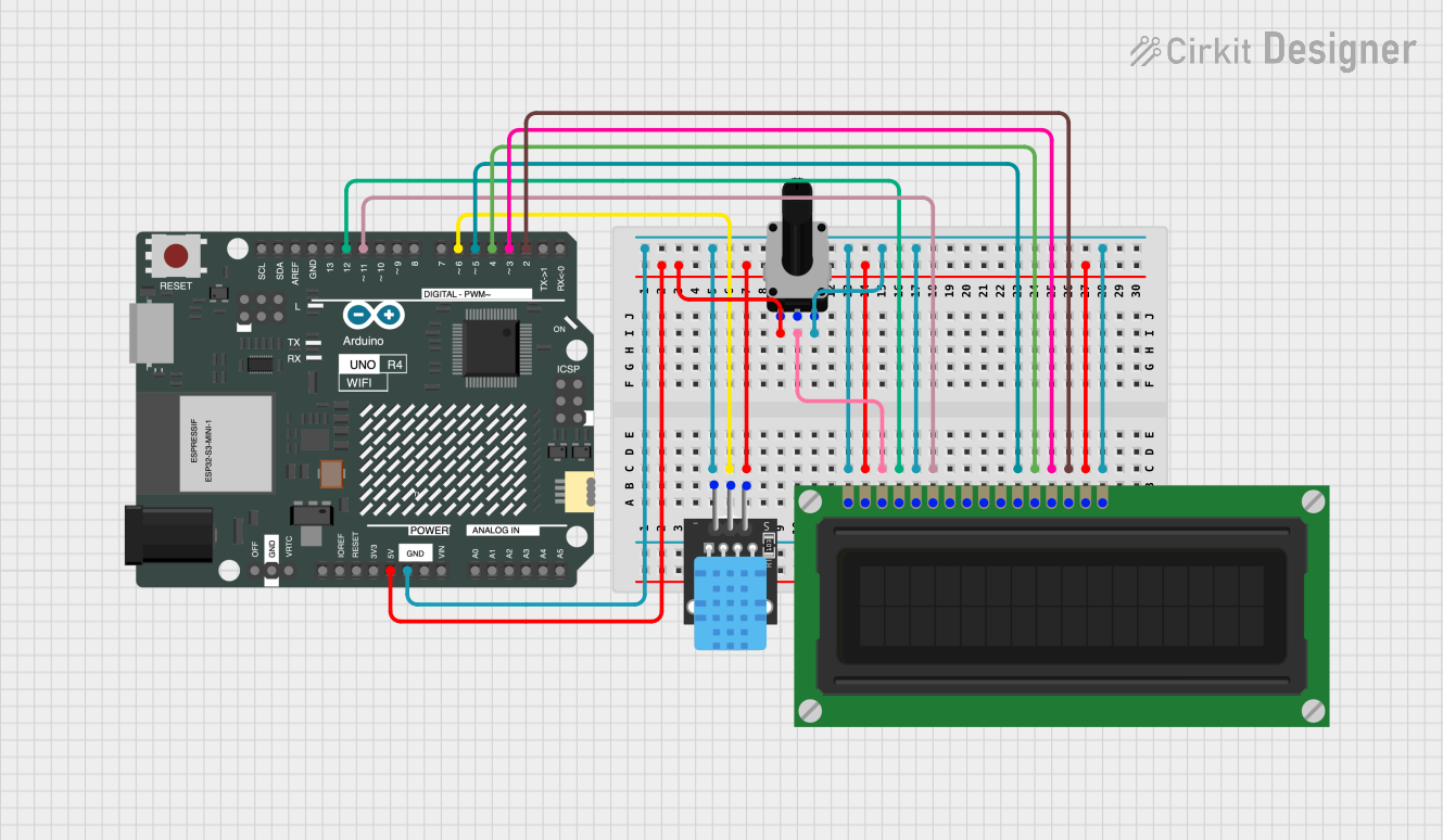
The circuit in question is designed to interface a DHT11 temperature and humidity sensor with an Arduino UNO R4 WiFi microcontroller, display the sensor readings on an LCD display, and adjust the display contrast using a rotary potentiometer. The Arduino UNO R4 WiFi is the central processing unit of the circuit, reading data from the DHT11 sensor and controlling the LCD display to show temperature and humidity values. The rotary potentiometer is used to adjust the contrast of the LCD display for better visibility.
Component List
DHT11 Temperature and Humidity Sensor
- Description: A basic, low-cost digital temperature and humidity sensor.
- Pins: 5V, S (Signal), GND
Arduino UNO R4 WiFi
- Description: A microcontroller board based on the ATmega328 with integrated WiFi capabilities.
- Pins: Multiple GPIOs, Power, Analog, and Communication pins.
LCD Display (16 pin)
- Description: A 16x2 character LCD display for showing text.
- Pins: VSS, VDD, VO, RS, R_W, E, DB0-DB7, A, K
Rotary Potentiometer
- Description: A variable resistor with a 10k Ohm value, typically used for adjusting voltage.
- Pins: leg1, wiper, leg2
- Properties: Resistance: 10,000 Ohms
Wiring Details
DHT11 Temperature and Humidity Sensor
- 5V: Connected to the 5V power supply from the Arduino UNO R4 WiFi.
- S (Signal): Connected to digital pin D6 on the Arduino UNO R4 WiFi.
- GND: Connected to the ground (GND) shared with other components.
Arduino UNO R4 WiFi
- GND: Common ground for the circuit.
- 5V: Provides power to the DHT11 sensor and the LCD display.
- D6: Receives the signal from the DHT11 sensor.
- D2-D5: Control the data pins DB7-DB4 of the LCD display.
- D11: Connected to the enable (E) pin of the LCD display.
- D12: Connected to the register select (RS) pin of the LCD display.
LCD Display (16 pin)
- VSS: Connected to the ground (GND).
- VDD: Connected to the 5V power supply.
- VO: Contrast adjustment connected to the wiper of the rotary potentiometer.
- RS: Connected to digital pin D12 on the Arduino UNO R4 WiFi.
- R_W: Connected to the ground (GND) to set the LCD to write mode.
- E: Connected to digital pin D11 on the Arduino UNO R4 WiFi.
- DB4-DB7: Connected to digital pins D5-D2 on the Arduino UNO R4 WiFi respectively.
- A: Anode for the backlight, connected to the 5V power supply.
- K: Cathode for the backlight, connected to the ground (GND).
Rotary Potentiometer
- leg1: Connected to the 5V power supply.
- wiper: Connected to the VO pin of the LCD display for contrast control.
- leg2: Connected to the ground (GND).
Documented Code
#include <DHT.h>
#include <LiquidCrystal.h>

// Define the DHT11 sensor pin and type
#define DHTPIN 6
#define DHTTYPE DHT11

// Initialize the DHT sensor
DHT dht(DHTPIN, DHTTYPE);

// Initialize the LCD (RS, E, D4, D5, D6, D7)
LiquidCrystal lcd(12, 11, 5, 4, 3, 2);

void setup() {
  // Start the DHT sensor
  dht.begin();

  // Start the LCD
  lcd.begin(16, 2);

  // Print a message to the LCD
  lcd.print("Temp & Humidity");
}

void loop() {
  // Wait a few seconds between measurements
  delay(2000);

  // Read temperature and humidity
  float h = dht.readHumidity();
  float t = dht.readTemperature();

  // Check if any reads failed and exit early (to try again)
  if (isnan(h) || isnan(t)) {
    lcd.setCursor(0, 1);
    lcd.print("Error reading");
    return;
  }

  // Clear the second line
  lcd.setCursor(0, 1);
  lcd.print("                ");

  // Set cursor to the beginning of the second line
  lcd.setCursor(0, 1);

  // Print temperature and humidity
  lcd.print("T:");
  lcd.print(t);
  lcd.print("C H:");
  lcd.print(h);
  lcd.print("%");
}
This code is designed to run on the Arduino UNO R4 WiFi microcontroller. It initializes the DHT11 sensor and the LCD display, reads temperature and humidity from the sensor, and displays the values on the LCD. If the sensor fails to provide valid readings, an error message is displayed.