
Arduino UNO Controlled Ultrasonic Distance Measurement with RGB LED Indicators
View and Edit Project In Cirkit Designer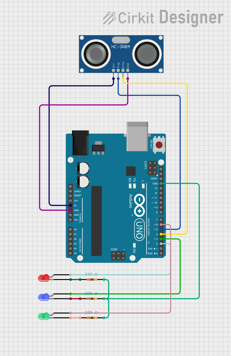
Circuit Documentation
Summary
The circuit in question is designed around an Arduino UNO microcontroller and includes a variety of components such as LEDs, resistors, and an HC-SR04 Ultrasonic Sensor. The Arduino UNO controls the LEDs and interfaces with the ultrasonic sensor to possibly measure distance or detect objects. The LEDs are connected through resistors to limit the current, and the sensor is powered directly from the Arduino's 5V supply.
Component List
Arduino UNO
- Description: A microcontroller board based on the ATmega328P.
- Pins: UNUSED, IOREF, Reset, 3.3V, 5V, GND, Vin, A0-A5, SCL, SDA, AREF, D0-D13.
- Purpose: Acts as the central processing unit of the circuit, controlling the LEDs and reading data from the ultrasonic sensor.
Resistor (220 Ohms)
- Description: A passive two-terminal electrical component that implements electrical resistance as a circuit element.
- Properties: Resistance value of 220 Ohms.
LED: Two Pin (Green, Red, Blue)
- Description: Light Emitting Diodes of different colors.
- Pins: Cathode, Anode.
- Purpose: To provide visual indicators, possibly for signaling or status display.
HC-SR04 Ultrasonic Sensor
- Description: An ultrasonic ranging module that provides 2cm to 400cm non-contact measurement function.
- Pins: VCC, TRIG, ECHO, GND.
- Purpose: To measure distances or detect the presence of objects.
Wiring Details
Arduino UNO
- 5V to HC-SR04 Ultrasonic Sensor VCC
- GND to HC-SR04 Ultrasonic Sensor GND
- GND to all resistor pin2
- D6 to Green LED anode
- D5 to HC-SR04 Ultrasonic Sensor TRIG
- D4 to HC-SR04 Ultrasonic Sensor ECHO
- D3 to Blue LED anode
- D2 to Red LED anode
Resistor (220 Ohms)
- One end (pin1) to the cathode of the corresponding LED
- Other end (pin2) to Arduino UNO GND
LED: Two Pin (Green, Red, Blue)
- Anode to specified Arduino UNO digital pin (D6 for Green, D3 for Blue, D2 for Red)
- Cathode to one end of a 220 Ohm resistor
HC-SR04 Ultrasonic Sensor
- VCC to Arduino UNO 5V
- GND to Arduino UNO GND
- TRIG to Arduino UNO D5
- ECHO to Arduino UNO D4
Documented Code
Arduino UNO Code (sketch.ino)
void setup() {
  // put your setup code here, to run once:

}

void loop() {
  // put your main code here, to run repeatedly:

}
Additional Notes
- The provided code is a template and does not contain any functional implementation. It needs to be populated with the logic for controlling the LEDs and interfacing with the HC-SR04 Ultrasonic Sensor.
- The
setup()function is intended for initial configuration, and theloop()function will contain the main operational code that runs repeatedly. - The actual behavior of the LEDs and the data handling from the ultrasonic sensor will be determined by the code that is to be written in these functions.