Cirkit Designer
Your all-in-one circuit design IDE
Home /
Project Documentation
Arduino UNO-Based Security System with Motion and Flame Detection and GSM Notification
Circuit Documentation
Summary
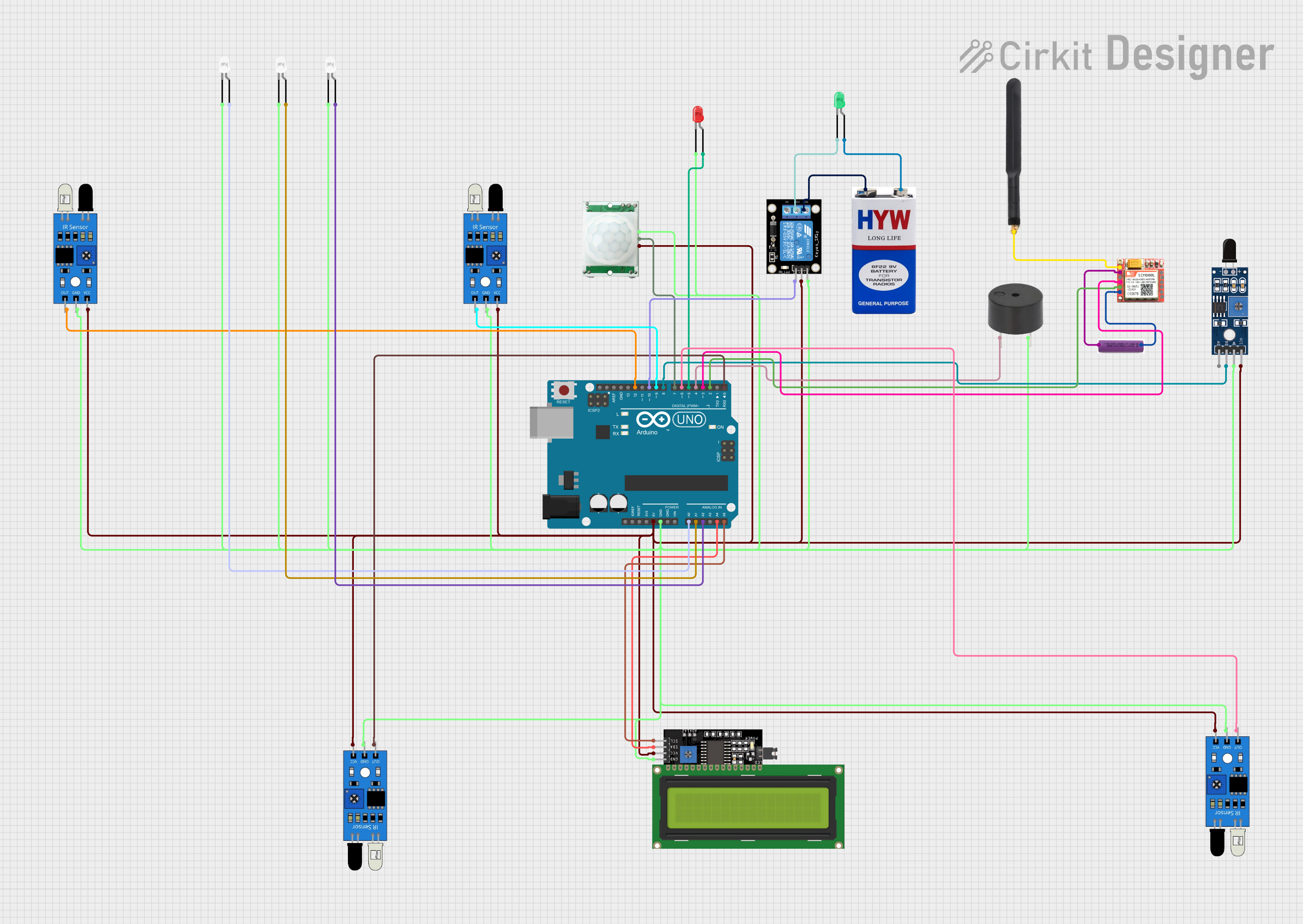
This circuit integrates various components including an Arduino UNO, sensors (PIR/Motion, IR, and Flame), a buzzer, a SIM800L module, a relay module, LEDs, an LCD display, and power sources (3.7v and 9V batteries). The Arduino UNO serves as the central microcontroller, interfacing with the sensors to detect environmental changes, controlling LEDs and a buzzer for alerts, and communicating via the SIM800L module. The relay module is used to switch higher power loads, and the LCD display provides a user interface.
Component List
Arduino UNO
- Microcontroller board based on the ATmega328P
- Used as the main controller for the circuit
Sensor SHT113 Flame
- Flame detection sensor with digital and analog outputs
- Monitors for the presence of flames or fire
Buzzer
- An electromechanical component that produces sound
- Used for audible alerts or alarms
SIM800L
- GSM/GPRS module for cellular communication
- Enables SMS and network connectivity for the circuit
3.7v Battery
- Power source for the SIM800L module
KY-019 Relay Module 1 Channel
- Electromechanical switch that controls a high power circuit with a low power signal
- Used to control devices that require higher voltages
IR Sensors
- Infrared sensors for object detection or distance measurement
- Multiple instances used for various detection purposes
PIR/Motion Sensor
- Passive infrared sensor that detects motion
- Used for security or automation applications
9V Battery
- Power source for the relay module
LEDs (Red, White, Green)
- Light Emitting Diodes of various colors
- Used as indicators or for illumination
4G Antenna
- Antenna for enhancing cellular network signal strength
- Connected to the SIM800L module
LCD Display 16x4 I2C
- Alphanumeric liquid crystal display with I2C interface
- Provides a user interface for displaying information
Wiring Details
Arduino UNO
- 5V and GND pins provide power to PIR/Motion Sensor, IR Sensors, LCD Display, Relay Module, and Flame Sensor
- Analog pins A0, A1, A2 are connected to white LEDs
- I2C pins A4 (SDA) and A5 (SCL) are connected to the LCD Display
- Digital pins D0, D2-D12 are interfaced with various sensors, the buzzer, the relay module, and the SIM800L module
Sensor SHT113 Flame
- VCC and GND for power supply
- D0 connected to Arduino UNO D8
Buzzer
- PIN connected to Arduino UNO D4
- GND for ground connection
SIM800L
- VCC and GND connected to 3.7v Battery
- RXD and TXD connected to Arduino UNO D3 and D2 respectively
- NFT connected to 4G Antenna
KY-019 Relay Module 1 Channel
- S connected to Arduino UNO D10
- 5V and GND for power supply
- COM connected to the cathode of the green LED
- NO connected to the 9V battery
IR Sensors
- VCC and GND for power supply
- OUT connected to various digital pins on the Arduino UNO (D0, D6, D9, D12)
PIR/Motion Sensor
- VCC and GND for power supply
- OUTPUT connected to Arduino UNO D7
LEDs
- Anodes connected to various Arduino UNO analog pins (A0, A1, A2)
- Cathodes connected to GND
LCD Display 16x4 I2C
- SDA and SCL connected to Arduino UNO A4 and A5
- VCC and GND for power supply
Power Sources
- 3.7v Battery connected to SIM800L VCC and GND
- 9V Battery connected to Relay Module NO and the anode of the green LED
Documented Code
Arduino UNO Code (sketch.ino)
void setup() {
  // put your setup code here, to run once:

}

void loop() {
  // put your main code here, to run repeatedly:

}
Note: The provided code is a template and does not contain any functional code. It needs to be populated with the logic to control the components based on the circuit's requirements.