
Arduino-Based Automated Medicine Dispenser with RTC and I2C LCD
View and Edit Project In Cirkit Designer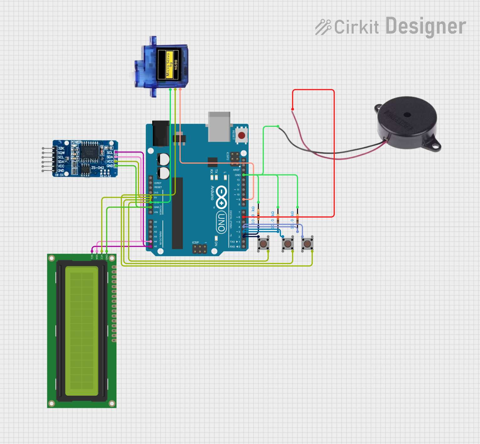
Circuit Documentation
Summary
This circuit is designed to manage a medication dispensing system. It includes an Arduino UNO microcontroller, a 16x2 I2C LCD for display, a buzzer for alerts, a micro servo motor for dispensing pills, an RTC DS3231 for real-time clock functionality, and multiple pushbuttons and resistors for user input and control.
Component List
Arduino UNO
- Description: Microcontroller board based on the ATmega328P.
- Pins: UNUSED, IOREF, Reset, 3.3V, 5V, GND, Vin, A0, A1, A2, A3, A4, A5, SCL, SDA, AREF, D13, D12, D11, D10, D9, D8, D7, D6, D5, D4, D3, D2, D1, D0
16x2 I2C LCD
- Description: 16x2 character LCD display with I2C interface.
- Pins: GND, VCC, SDA, SCL
Buzzer
- Description: Simple piezoelectric buzzer.
- Pins: POSITIVE, NEGATIVE
Micro servo 9G
- Description: Small servo motor for precise control.
- Pins: GND, +5V, PWM
RTC DS3231
- Description: Real-Time Clock module with I2C interface.
- Pins: 32K, SQW, SCL, SDA, VCC, GND
Pushbutton
- Description: Momentary pushbutton switch.
- Pins: Pin 3 (out), Pin 4 (out), Pin 1 (in), Pin 2 (in)
Resistor
- Description: Resistor with a resistance of 10k Ohms.
- Pins: pin1, pin2
Wiring Details
Arduino UNO
5V connected to:
- VCC of RTC DS3231
- VCC of 16x2 I2C LCD
- +5V of Micro servo 9G
- Pin 4 (out) of Pushbutton 1
- Pin 4 (out) of Pushbutton 2
- Pin 4 (out) of Pushbutton 3
GND connected to:
- GND of RTC DS3231
- GND of 16x2 I2C LCD
- GND of Micro servo 9G
- NEGATIVE of Buzzer
- pin2 of Resistor 1
- pin2 of Resistor 2
- pin2 of Resistor 3
A4 connected to:
- SDA of RTC DS3231
- SDA of 16x2 I2C LCD
A5 connected to:
- SCL of RTC DS3231
- SCL of 16x2 I2C LCD
D9 connected to:
- PWM of Micro servo 9G
D6 connected to:
- POSITIVE of Buzzer
D4 connected to:
- Pin 1 (in) of Pushbutton 1
- pin1 of Resistor 1
D3 connected to:
- Pin 1 (in) of Pushbutton 2
- pin1 of Resistor 2
D2 connected to:
- Pin 1 (in) of Pushbutton 3
- pin1 of Resistor 3
16x2 I2C LCD
- GND connected to GND of Arduino UNO
- VCC connected to 5V of Arduino UNO
- SDA connected to A4 of Arduino UNO
- SCL connected to A5 of Arduino UNO
Buzzer
- POSITIVE connected to D6 of Arduino UNO
- NEGATIVE connected to GND of Arduino UNO
Micro servo 9G
- GND connected to GND of Arduino UNO
- +5V connected to 5V of Arduino UNO
- PWM connected to D9 of Arduino UNO
RTC DS3231
- GND connected to GND of Arduino UNO
- VCC connected to 5V of Arduino UNO
- SDA connected to A4 of Arduino UNO
- SCL connected to A5 of Arduino UNO
Pushbutton 1
- Pin 4 (out) connected to 5V of Arduino UNO
- Pin 1 (in) connected to D4 of Arduino UNO
- Pin 1 (in) connected to pin1 of Resistor 1
Pushbutton 2
- Pin 4 (out) connected to 5V of Arduino UNO
- Pin 1 (in) connected to D3 of Arduino UNO
- Pin 1 (in) connected to pin1 of Resistor 2
Pushbutton 3
- Pin 4 (out) connected to 5V of Arduino UNO
- Pin 1 (in) connected to D2 of Arduino UNO
- Pin 1 (in) connected to pin1 of Resistor 3
Resistor 1
- pin1 connected to Pin 1 (in) of Pushbutton 1
- pin2 connected to GND of Arduino UNO
Resistor 2
- pin1 connected to Pin 1 (in) of Pushbutton 2
- pin2 connected to GND of Arduino UNO
Resistor 3
- pin1 connected to Pin 1 (in) of Pushbutton 3
- pin2 connected to GND of Arduino UNO
Documented Code
#include <Wire.h>
#include <RTClib.h>
#include <Servo.h>
#include <LiquidCrystal_I2C.h>

// Initialize components
RTC_DS3231 rtc; // For Real-Time Clock module
Servo servo;    // For servo motor
LiquidCrystal_I2C lcd(0x27, 16, 2); // I2C address and dimensions of LCD

// Buzzer pin and servo settings
const int buzzerPin = 8;
const int servoPin = 9;

// Preset medicine timings (hh:mm format)
String timings[] = {"08:00", "14:00", "21:09"};
bool medicineDispensed = false; // To track if the medicine was dispensed for the current time

void setup() {
  // Initialize serial monitor for debugging
  Serial.begin(9600);

  // Initialize components
  lcd.begin(16,2);
  lcd.backlight();
  servo.attach(servoPin);
  pinMode(buzzerPin, OUTPUT);

  // Start the RTC
  if (!rtc.begin()) {
    lcd.print("RTC not found!");
    while (1); // Stop execution
  }

  // Check if RTC is running
  if (rtc.lostPower()) {
    lcd.print("RTC is reset!");
    rtc.adjust(DateTime(F(__DATE__), F(__TIME__))); // Adjust to compile time
  }

  // Initialize the servo position
  servo.write(0); // Start position: pill plate is hidden
}

void loop() {
  // Get current time
  DateTime now = rtc.now();
  String currentTime = formatTime(now.hour(), now.minute());

  // Check if it's time for medication
  for (String timing : timings) {
    if (currentTime == timing && !medicineDispensed) {
      // Alert user and dispense medicine
      alertUser();
      delay(5000); // Buzzer duration: 5 seconds
      dispenseMedicine();
      medicineDispensed = true; // Mark as dispensed
    }
  }

  // Reset the flag after 1 minute
  if (millis() % 60000 == 0) {
    medicineDispensed = false;
  }

  delay(1000); // Wait 1 second before next check
}

// Function to alert the user
void alertUser() {
  lcd.clear();
  lcd.print("Take Medicine!");
  digitalWrite(buzzerPin, HIGH);
  delay(5000); // Keep buzzer on for 5 seconds
  digitalWrite(buzzerPin, LOW);
}

// Function to dispense the medicine
void dispenseMedicine() {
  delay(30000); // Wait 30 seconds after buzzer
  servo.write(90); // Rotate servo to expose the pill plate
  delay(5000); // Keep plate open for 5 seconds
  servo.write(0); // Rotate servo back to hide the plate
  lcd.clear();
  lcd.print("Medicine Taken");
}

// Helper function to format time into hh:mm
String formatTime(int hour, int minute) {
  char timeStr[6];
  sprintf(timeStr, "%02d:%02d", hour, minute);
  return String(timeStr);
}
This documentation provides a comprehensive overview of the circuit, including a summary, detailed component list, wiring details, and the embedded code used in the Arduino UNO microcontroller.