
Arduino UNO Controlled GSM Interface with LCD Feedback and Relay Switching
View and Edit Project In Cirkit Designer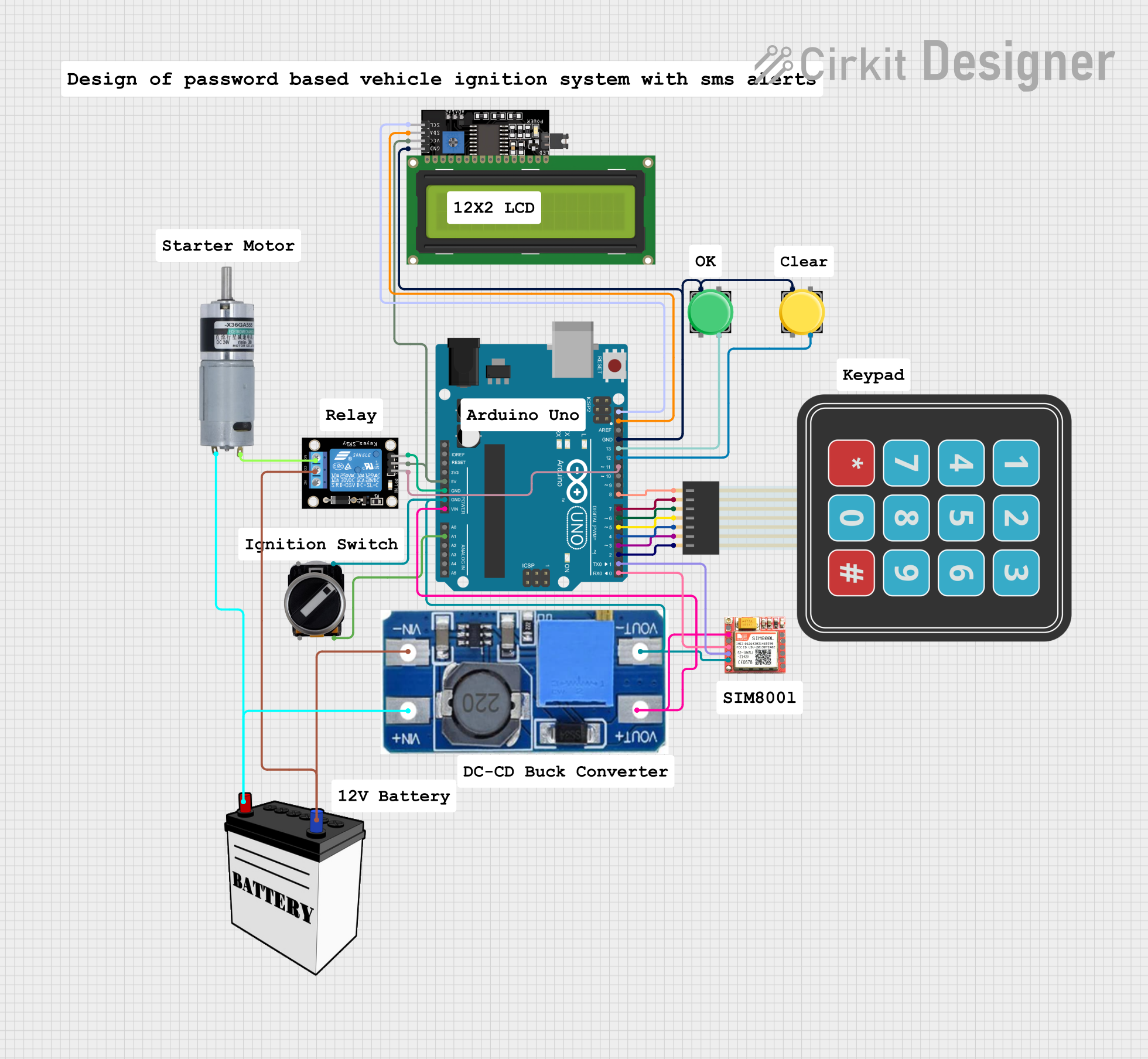
Circuit Documentation
Summary
This document provides a detailed overview of a circuit that includes an Arduino UNO as the central microcontroller, interfaced with various components such as an LCD Display, a Relay module, a Membrane Matrix Keypad, a SIM800L GSM module, pushbuttons, a 3 Position Switch, a Step Up Boost Power Converter, a 12V Battery, and an MRB Planetary Gearbox Motor. The circuit is designed to perform multiple functions, which could include user input through the keypad, displaying information on the LCD, controlling power to the motor via the relay, and communicating over GSM with the SIM800L module.
Component List
Arduino UNO
- Microcontroller board based on the ATmega328P
- Pins: UNUSED, IOREF, Reset, 3.3V, 5V, GND, Vin, A0-A5, SCL, SDA, AREF, D0-D13
3 Position Switch
- A switch with three selectable positions
- Pins: 23, 11, 24, 12
Membrane Matrix Keypad
- A 4x3 matrix keypad for user input
- Pins: Row 1-4, Column 1-3
SIM800L GSM Module
- A GSM/GPRS module for cellular communication
- Pins: NFT, RING, VCC, DTR, RST, MIC+, RXD, MIC-, TXD, SPK+, GND, SPK-
Pushbutton (x2)
- A simple pushbutton for user interaction
- Pins: Pin 1-4
12V Battery
- A power source for the circuit
- Pins: VCC, GND
LCD Display 16x4 I2C
- An alphanumeric liquid crystal display with I2C interface
- Pins: SCL, SDA, VCC, GND
KY-019 Relay Module 1 Channel
- A relay module for controlling high power devices
- Pins: S, 5V, GND, NC, COM, NO
Step Up Boost Power Converter, Adjustable Voltage Regulator
- A voltage regulator to step up the voltage
- Pins: VOUT+, VOUT-, VIN+, VIN-
MRB Planetary Gearbox Motor
- A motor with a gearbox for high torque applications
- Pins: +, -
Wiring Details
Arduino UNO
- 5V connected to LCD Display VCC and Relay Module 5V
- GND connected to Relay Module GND, 3 Position Switch, SIM800L GND, LCD Display GND, both Pushbuttons Pin 1
- Vin connected to Step Up Boost Power Converter VOUT+
- A1 connected to 3 Position Switch
- SCL connected to LCD Display SCL
- SDA connected to LCD Display SDA
- D13 connected to Pushbutton (Instance 2) Pin 4
- D12 connected to Pushbutton (Instance 1) Pin 4
- D11 connected to Relay Module S
- D8-D2 connected to Membrane Matrix Keypad Rows 1-4 and Columns 1-3 respectively
- D1 connected to SIM800L TXD
- D0 connected to SIM800L RXD
3 Position Switch
- Pin 11 connected to Arduino GND and Step Up Boost Power Converter VOUT-
- Pin 12 connected to Arduino A1
Membrane Matrix Keypad
- Rows 1-4 connected to Arduino D8-D5
- Columns 1-3 connected to Arduino D4-D2
SIM800L GSM Module
- VCC connected to Step Up Boost Power Converter VOUT+
- GND connected to 3 Position Switch and Arduino GND
- TXD connected to Arduino D1
- RXD connected to Arduino D0
Pushbuttons
- Pin 1 connected to Arduino GND
- Pin 4 connected to Arduino D13 (Instance 2) and D12 (Instance 1)
12V Battery
- VCC connected to Step Up Boost Power Converter VIN+
- GND connected to Step Up Boost Power Converter VIN- and Relay Module COM
LCD Display 16x4 I2C
- SCL connected to Arduino SCL
- SDA connected to Arduino SDA
- VCC connected to Arduino 5V
- GND connected to Arduino GND
KY-019 Relay Module 1 Channel
- S connected to Arduino D11
- 5V connected to Arduino 5V
- GND connected to Arduino GND
- COM connected to 12V Battery GND
- NO connected to MRB Planetary Gearbox Motor -
Step Up Boost Power Converter, Adjustable Voltage Regulator
- VOUT+ connected to Arduino Vin and SIM800L VCC
- VOUT- connected to 3 Position Switch and Arduino GND
- VIN+ connected to 12V Battery VCC and MRB Planetary Gearbox Motor +
- VIN- connected to 12V Battery GND
MRB Planetary Gearbox Motor
-
- connected to Step Up Boost Power Converter VIN+
-
- connected to Relay Module NO
Documented Code
Arduino UNO Code (sketch.ino)
void setup() {
  // put your setup code here, to run once:

}

void loop() {
  // put your main code here, to run repeatedly:

}
Additional Notes
- The provided code is a template and does not contain any functional code specific to the circuit's operation.
- Further implementation is required to control and interact with the connected components based on the circuit's intended functionality.