
Circuit Documentation
Summary
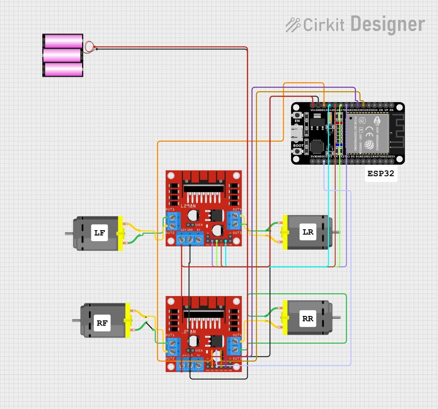
This circuit is designed to control multiple DC motors using an ESP32 microcontroller and L298N motor drivers. The ESP32 is programmed to connect to a Wi-Fi network and provide a web interface for controlling the motors. The circuit also includes a 12V battery to power the motors and motor drivers.
Component List
ESP32 (30 pin)
- Description: A powerful microcontroller with built-in Wi-Fi and Bluetooth capabilities.
- Pins: EN, VP, VN, D34, D35, D32, D33, D25, D26, D27, D14, D12, D13, GND, Vin, D23, D22, TX0, RX0, D21, D19, D18, D5, TX2, RX2, D4, D2, D15, 3V3
DC Motor
- Description: A simple DC motor.
- Pins: pin 1, pin 2
L298N DC Motor Driver
- Description: A dual H-Bridge motor driver that allows control of two DC motors.
- Pins: OUT1, OUT2, 12V, GND, 5V, OUT3, OUT4, 5V-ENA-JMP-I, 5V-ENA-JMP-O, +5V-J1, +5V-J2, ENA, IN1, IN2, IN3, IN4, ENB
Battery 12V
- Description: A 12V battery to power the motors and motor drivers.
- Pins: +, -
Comment
- Description: Placeholder for comments in the circuit.
- Pins: None
Wiring Details
ESP32 (30 pin)
- D32 connected to L298N DC Motor Driver (IN3)
- D33 connected to L298N DC Motor Driver (IN4)
- D26 connected to L298N DC Motor Driver (IN1)
- D27 connected to L298N DC Motor Driver (IN2)
- D14 connected to L298N DC Motor Driver (IN3)
- D12 connected to L298N DC Motor Driver (IN4)
- D13 connected to L298N DC Motor Driver (IN1)
- GND connected to L298N DC Motor Driver (GND) and Battery 12V (-)
- Vin connected to L298N DC Motor Driver (12V) and Battery 12V (+)
- D15 connected to L298N DC Motor Driver (IN2)
DC Motor
Motor 1
- pin 1 connected to L298N DC Motor Driver (OUT3)
- pin 2 connected to L298N DC Motor Driver (OUT4)
Motor 2
- pin 1 connected to L298N DC Motor Driver (OUT1)
- pin 2 connected to L298N DC Motor Driver (OUT2)
Motor 3
- pin 1 connected to L298N DC Motor Driver (OUT1)
- pin 2 connected to L298N DC Motor Driver (OUT2)
Motor 4
- pin 1 connected to L298N DC Motor Driver (OUT3)
- pin 2 connected to L298N DC Motor Driver (OUT4)
L298N DC Motor Driver
Driver 1
- IN1 connected to ESP32 (D26)
- IN2 connected to ESP32 (D27)
- IN3 connected to ESP32 (D14)
- IN4 connected to ESP32 (D12)
- GND connected to ESP32 (GND) and Battery 12V (-)
- 12V connected to ESP32 (Vin) and Battery 12V (+)
- OUT1 connected to DC Motor (pin 1)
- OUT2 connected to DC Motor (pin 2)
- OUT3 connected to DC Motor (pin 1)
- OUT4 connected to DC Motor (pin 2)
Driver 2
- IN1 connected to ESP32 (D13)
- IN2 connected to ESP32 (D15)
- IN3 connected to ESP32 (D32)
- IN4 connected to ESP32 (D33)
- GND connected to ESP32 (GND) and Battery 12V (-)
- 12V connected to ESP32 (Vin) and Battery 12V (+)
- OUT1 connected to DC Motor (pin 1)
- OUT2 connected to DC Motor (pin 2)
- OUT3 connected to DC Motor (pin 1)
- OUT4 connected to DC Motor (pin 2)
Battery 12V
- + connected to ESP32 (Vin) and L298N DC Motor Driver (12V)
- - connected to ESP32 (GND) and L298N DC Motor Driver (GND)
Code Documentation
#include <WiFi.h>
#include <ESPAsyncWebServer.h>
#include <Servo.h>

// Motor pins (L298N Motor Driver)
const int motor1Pin1 = 26;
const int motor1Pin2 = 27;
const int motor2Pin1 = 14;
const int motor2Pin2 = 12;
const int motor3Pin1 = 13;
const int motor3Pin2 = 15;
const int motor4Pin1 = 32;
const int motor4Pin2 = 33;

// Servo pins
Servo servo1;
Servo servo2;
Servo servo3;
Servo servo4;

const int servo1Pin = 2;
const int servo2Pin = 4;
const int servo3Pin = 5;
const int servo4Pin = 18;

// Wi-Fi credentials
const char *ssid = "YOUR_SSID";
const char *password = "YOUR_PASSWORD";

// Server object
AsyncWebServer server(80);

// Function to stop all motors
void stopMotors() {
  digitalWrite(motor1Pin1, LOW);
  digitalWrite(motor1Pin2, LOW);
  digitalWrite(motor2Pin1, LOW);
  digitalWrite(motor2Pin2, LOW);
  digitalWrite(motor3Pin1, LOW);
  digitalWrite(motor3Pin2, LOW);
  digitalWrite(motor4Pin1, LOW);
  digitalWrite(motor4Pin2, LOW);
}

void setup() {
  // Initialize Serial Monitor
  Serial.begin(115200);

  // Setup motor pins
  pinMode(motor1Pin1, OUTPUT);
  pinMode(motor1Pin2, OUTPUT);
  pinMode(motor2Pin1, OUTPUT);
  pinMode(motor2Pin2, OUTPUT);
  pinMode(motor3Pin1, OUTPUT);
  pinMode(motor3Pin2, OUTPUT);
  pinMode(motor4Pin1, OUTPUT);
  pinMode(motor4Pin2, OUTPUT);

  // Attach servos
  servo1.attach(servo1Pin);
  servo2.attach(servo2Pin);
  servo3.attach(servo3Pin);
  servo4.attach(servo4Pin);

  // Connect to Wi-Fi
  WiFi.begin(ssid, password);
  while (WiFi.status() != WL_CONNECTED) {
    delay(1000);
    Serial.println("Connecting to WiFi...");
  }
  Serial.println("Connected to WiFi");

  // Setup web server routes
  server.on("/", HTTP_GET, [](AsyncWebServerRequest *request) {
    request->send(200, "text/plain", "Control your RC Car");
  });

  // Control routes (adjust as per app logic)
  server.on("/forward", HTTP_GET, [](AsyncWebServerRequest *request) {
    digitalWrite(motor1Pin1, HIGH);
    digitalWrite(motor1Pin2, LOW);
    digitalWrite(motor2Pin1, HIGH);
    digitalWrite(motor2Pin2, LOW);
    digitalWrite(motor3Pin1, HIGH);
    digitalWrite(motor3Pin2, LOW);
    digitalWrite(motor4Pin1, HIGH);
    digitalWrite(motor4Pin2, LOW);
    request->send(200, "text/plain", "Moving Forward");
  });

  server.on("/stop", HTTP_GET, [](AsyncWebServerRequest *request) {
    stopMotors();
    request->send(200, "text/plain", "Stopped");
  });

  server.begin();
}

void loop() {
  // Handle other actions like servo movement in response to app commands
}
This code sets up the ESP32 to control four DC motors and four servos. It connects to a Wi-Fi network and starts a web