
Raspberry Pi 5 Smart Weather Station with GPS and AI Integration
View and Edit Project In Cirkit Designer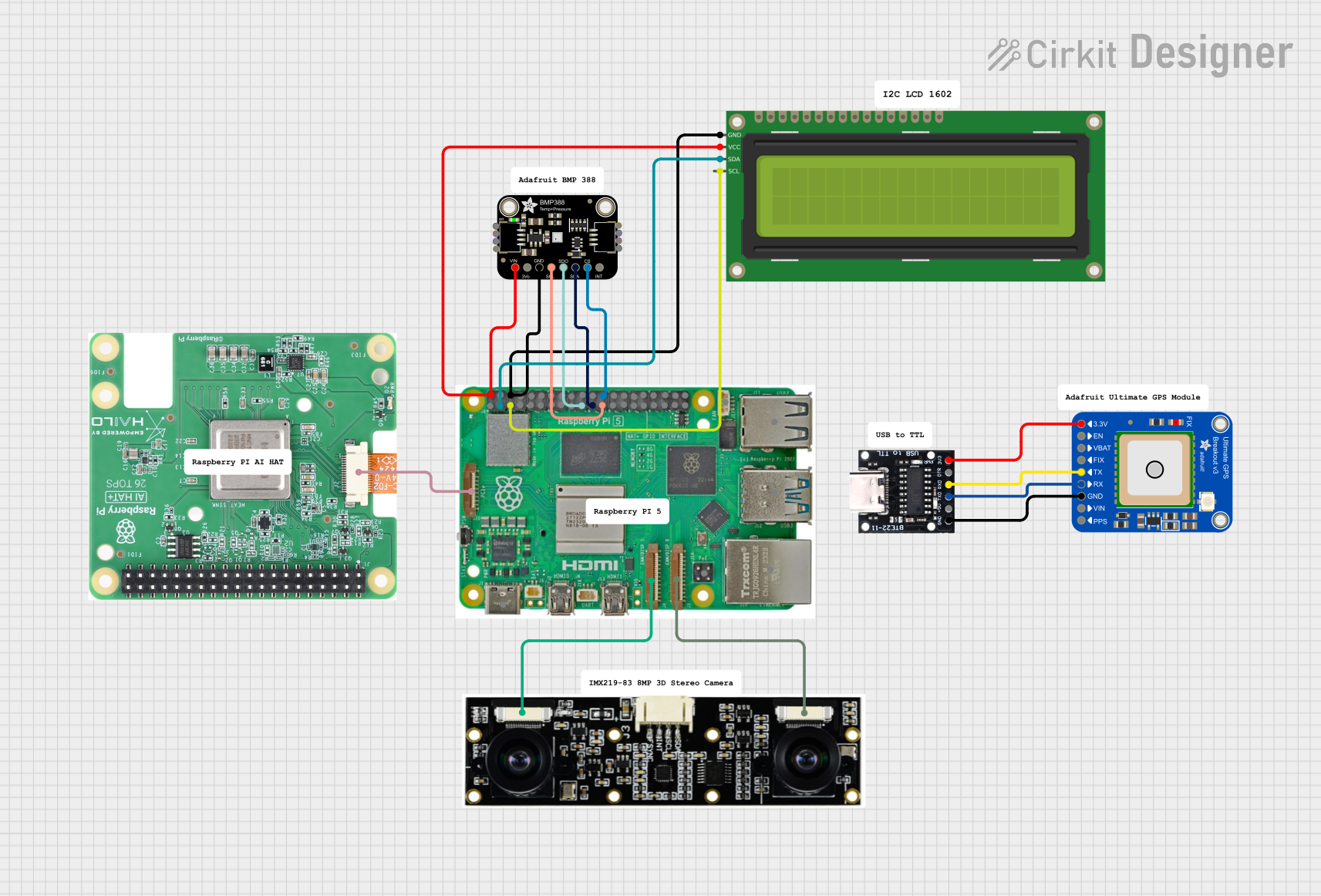
Circuit Documentation
Summary
This document provides a detailed overview of a circuit involving a Raspberry Pi 5, various sensors, a GPS module, a camera, and an LCD display. The circuit is designed to interface these components for data acquisition and display purposes. The document includes a component list, wiring details, and documented code for the microcontroller.
Component List
Raspberry Pi 5
- Description: A powerful single-board computer with multiple GPIO pins and interfaces.
- Pins: Type-C, Micro HDMI 1, Micro HDMI 2, Camera 1, Camera 2, PoE, Fan, PCIe, USB 3.0, USB 2.0, Ethernet, 5V, GND, 3.3V, GPIO 14, GPIO 15, GPIO 18, GPIO 23, GPIO 24, GPIO 25, GPIO 8, GPIO 7, GPIO 1, GPIO 12, GPIO 16, GPIO 20, GPIO 21, GPIO 2, GPIO 3, GPIO 4, GPIO 17, GPIO 27, GPIO 22, GPIO 10, GPIO 9, GPIO 11, GPIO 0, GPIO 5, GPIO 6, GPIO 13, GPIO 19, GPIO 26
Adafruit Ultimate GPS v3
- Description: A GPS module for precise location tracking.
- Pins: 1PPS, VIN, GND, RX, TX, FIX, VBACKUP, ENABLE, 3.3V
USB Serial TTL
- Description: A USB to TTL serial converter for communication with microcontrollers.
- Pins: GND, 5V, TX, RX, DTR, 3.3V
Adafruit BMP388
- Description: A barometric pressure sensor for environmental data collection.
- Pins: VCC, 3.3V, GND, SCK/SCL, SDO/ADR, SDI/SDA, CS, INT
IMX219-83 8MP 3D Stereo Camera
- Description: A high-resolution stereo camera for image and video capture.
- Pins: Camera 1, Camera 2
Raspberry Pi 5 AI Hat
- Description: An AI hat for the Raspberry Pi 5 to enhance AI capabilities.
- Pins: Input
16x2 I2C LCD
- Description: A 16x2 character LCD display with I2C interface.
- Pins: GND, VCC, SDA, SCL
Wiring Details
Raspberry Pi 5
- Camera 1 connected to IMX219-83 8MP 3D Stereo Camera Camera 2
- Camera 2 connected to IMX219-83 8MP 3D Stereo Camera Camera 1
- PCIe connected to Raspberry Pi 5 AI Hat Input
- 5V connected to 16x2 I2C LCD VCC and Adafruit BMP388 VCC
- GND connected to 16x2 I2C LCD GND and Adafruit BMP388 GND
- GPIO 8 connected to Adafruit BMP388 CS
- GPIO 2 connected to 16x2 I2C LCD SDA
- GPIO 3 connected to 16x2 I2C LCD SCL
- GPIO 10 connected to Adafruit BMP388 SDO/ADR
- GPIO 9 connected to Adafruit BMP388 SDI/SDA
- GPIO 11 connected to Adafruit BMP388 SCK/SCL
Adafruit Ultimate GPS v3
- GND connected to USB Serial TTL GND
- RX connected to USB Serial TTL TX
- TX connected to USB Serial TTL RX
- 3.3V connected to USB Serial TTL 3.3V
USB Serial TTL
- GND connected to Adafruit Ultimate GPS v3 GND
- TX connected to Adafruit Ultimate GPS v3 RX
- RX connected to Adafruit Ultimate GPS v3 TX
- 3.3V connected to Adafruit Ultimate GPS v3 3.3V
Adafruit BMP388
- VCC connected to Raspberry Pi 5 5V
- GND connected to Raspberry Pi 5 GND
- CS connected to Raspberry Pi 5 GPIO 8
- SDO/ADR connected to Raspberry Pi 5 GPIO 10
- SDI/SDA connected to Raspberry Pi 5 GPIO 9
- SCK/SCL connected to Raspberry Pi 5 GPIO 11
IMX219-83 8MP 3D Stereo Camera
- Camera 1 connected to Raspberry Pi 5 Camera 2
- Camera 2 connected to Raspberry Pi 5 Camera 1
Raspberry Pi 5 AI Hat
- Input connected to Raspberry Pi 5 PCIe
16x2 I2C LCD
- GND connected to Raspberry Pi 5 GND
- VCC connected to Raspberry Pi 5 5V
- SDA connected to Raspberry Pi 5 GPIO 2
- SCL connected to Raspberry Pi 5 GPIO 3
Documented Code
USB Serial TTL (Arduino Sketch)
void setup() {
  // put your setup code here, to run once:

}

void loop() {
  // put your main code here, to run repeatedly:

}
Documentation (Text File)
This document provides a comprehensive overview of the circuit, including the components used, their wiring details, and the code for the microcontroller.