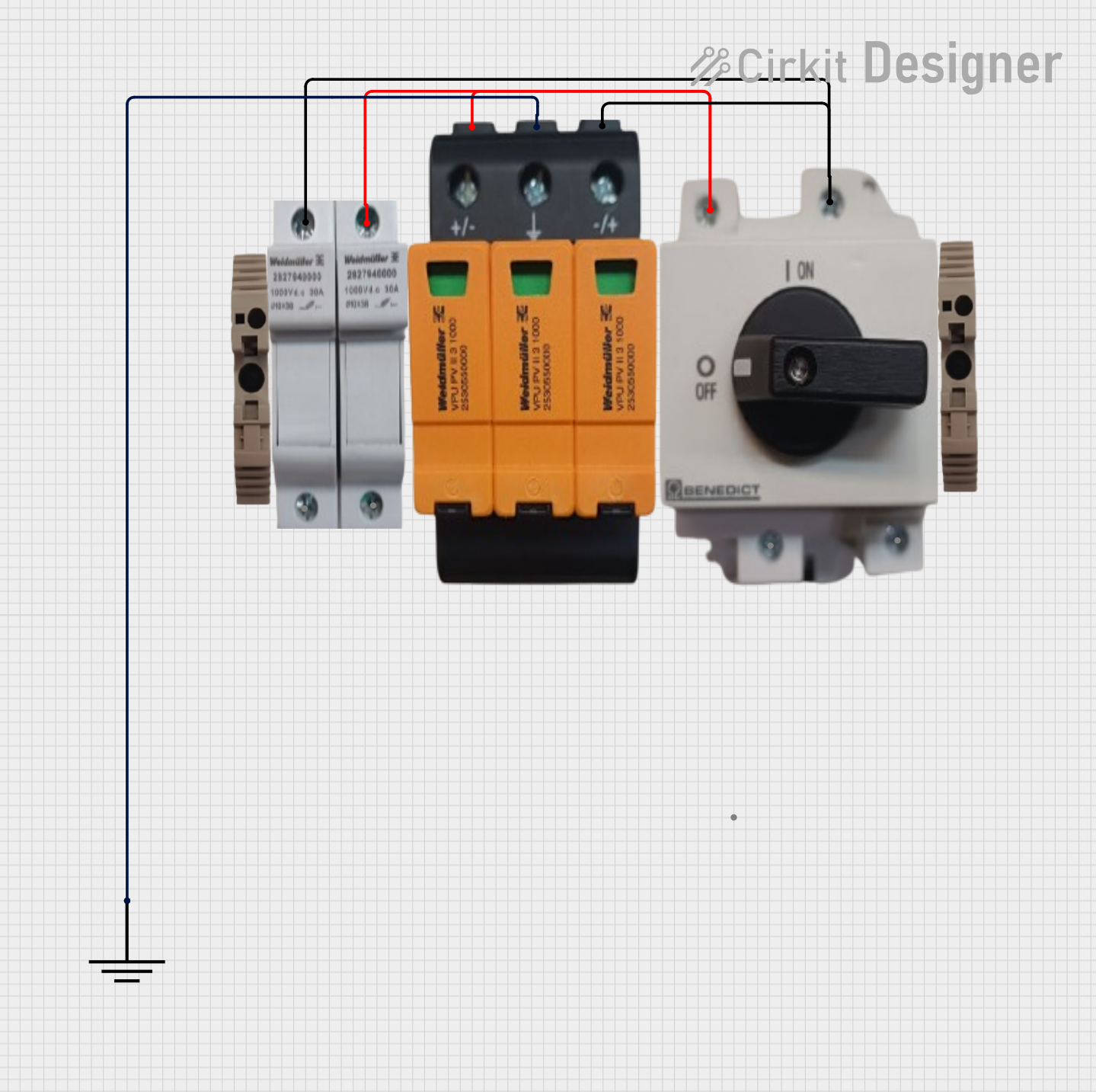
Basic Surge Protection Circuit with Benedict Switch

Circuit Documentation
Summary of the Circuit
The circuit in question appears to be a simple protection and switching circuit. It includes a Surge Protection Device (SPD), a Benedict Switch, and a Fuse Holder, which are typically used to protect electrical equipment from voltage spikes and to control the flow of electricity. Additionally, there are two End Brackets and a Ground component to complete the setup. The circuit does not include any microcontrollers or embedded code.
Component List
Fuse Holder
- Description: A device that contains and provides a mounting for a fuse.
- Purpose: To hold and provide an easy way to replace a fuse, which is used to protect the circuit from overcurrent.
SPD (Surge Protection Device)
- Description: A device designed to protect electrical equipment from voltage spikes.
- Purpose: To limit the voltage supplied to an electric device by either blocking or shorting to ground any unwanted voltages above a safe threshold.
Benedict Switch
- Description: A switch used to control the flow of electricity.
- Purpose: To manually open or close the electrical circuit.
End Bracket (x2)
- Description: A mechanical support component.
- Purpose: To provide structural support to the circuit components, likely used for mounting them onto a surface or panel.
Ground
- Description: A reference point in an electrical circuit from which voltages are measured, a common return path for electric current, or a direct physical connection to the Earth.
- Purpose: To provide a common return path for electric current and to ensure safety by dissipating excess current into the Earth.
Wiring Details
Fuse Holder
- Connections:
- Connected to the Benedict Switch.
- Connected to the SPD.
SPD (Surge Protection Device)
- Connections:
- Connected to the Fuse Holder.
- Connected to the Benedict Switch.
- Ground pin connected to the Ground component.
Benedict Switch
- Connections:
- Connected to the Fuse Holder.
- Connected to the SPD.
End Bracket
- Connections:
- No electrical connections, used for mechanical support.
Ground
- Connections:
- GND pin connected to the GND pin of the SPD.
Documented Code
There is no embedded code provided for this circuit as there are no microcontroller components included in the design. Therefore, no code documentation is necessary.
This documentation provides an overview of the circuit components and their interconnections. It should be noted that the exact wiring details, such as wire lengths, gauges, and routing, are not specified and should be determined based on the specific application and safety requirements.