
Arduino Nano-Based Automated Plant Watering System with Bluetooth Control and Soil Moisture Sensing
View and Edit Project In Cirkit Designer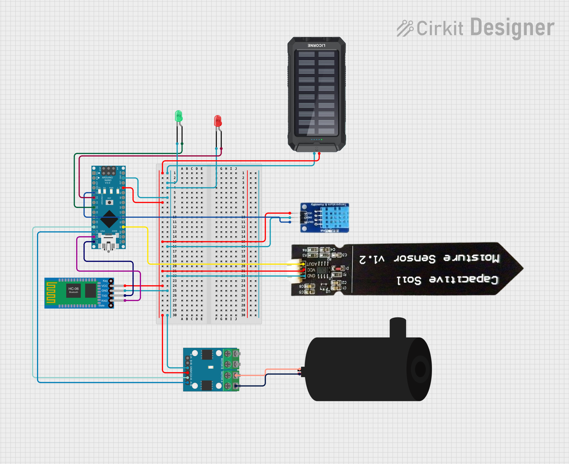
Circuit Documentation
Summary
The circuit in question is designed to interface an Arduino Nano with a variety of sensors and modules, including a Bluetooth HC-06 module, a DHT11 temperature and humidity sensor, a capacitive soil moisture sensor, two LEDs (red and green), a water pump, and a motor driver (L9110). The circuit is powered by a solar charger power bank, which provides a sustainable energy source. The Arduino Nano serves as the central processing unit, controlling the sensors, LEDs, and the water pump through the motor driver. Communication with external devices is facilitated by the Bluetooth module.
Component List
Arduino Nano
- Microcontroller board based on the ATmega328P
- Provides digital and analog I/O pins
- Used for controlling and processing data from sensors and modules
Bluetooth HC-06
- Bluetooth module for wireless communication
- Interfaces with the Arduino for remote data transmission and control
DHT11
- Temperature and humidity sensor
- Provides environmental data to the Arduino
Capacitive Soil Moisture Sensor V1.2
- Soil moisture sensor
- Measures the moisture level in the soil and provides data to the Arduino
LED: Two Pin (red)
- Red indicator LED
- Used for visual signaling or status indication
LED: Two Pin (green)
- Green indicator LED
- Used for visual signaling or status indication
Water Pump
- Electric pump for water circulation
- Controlled by the Arduino through the motor driver
L9110
- Motor driver module
- Drives the water pump based on signals from the Arduino
Solar Charger Power Bank
- Power supply for the circuit
- Provides a renewable energy source via solar power
Wiring Details
Arduino Nano
5Vconnected to the positive terminal of the Solar Charger Power BankGNDconnected to the negative terminal of the Solar Charger Power BankD2connected toDATApin of DHT11D3connected toanodeof the red LEDD5connected toanodeof the green LEDD9connected toA-IAof L9110D10connected toA-IBof L9110D11/MOSIconnected toRXDof Bluetooth HC-06D12/MISOconnected toTXDof Bluetooth HC-06A0connected toAOUTof Capacitive Soil Moisture Sensor V1.2
Bluetooth HC-06
VCCconnected to the positive terminal of the Solar Charger Power BankGNDconnected to the negative terminal of the Solar Charger Power BankTXDconnected toD12/MISOof Arduino NanoRXDconnected toD11/MOSIof Arduino Nano
DHT11
VCCconnected to the positive terminal of the Solar Charger Power BankGNDconnected to the negative terminal of the Solar Charger Power BankDATAconnected toD2of Arduino Nano
Capacitive Soil Moisture Sensor V1.2
VCCconnected to the positive terminal of the Solar Charger Power BankGNDconnected to the negative terminal of the Solar Charger Power BankAOUTconnected toA0of Arduino Nano
LED: Two Pin (red)
anodeconnected toD3of Arduino Nanocathodeconnected to the negative terminal of the Solar Charger Power Bank
LED: Two Pin (green)
anodeconnected toD5of Arduino Nanocathodeconnected to the negative terminal of the Solar Charger Power Bank
Water Pump
positiveconnected toMOTOR A-Aof L9110negativeconnected toMOTOR A-Bof L9110
L9110
VCCconnected to the positive terminal of the Solar Charger Power BankGNDconnected to the negative terminal of the Solar Charger Power BankA-IAconnected toD9of Arduino NanoA-IBconnected toD10of Arduino NanoMOTOR A-Aconnected topositiveof the water pumpMOTOR A-Bconnected tonegativeof the water pump
Solar Charger Power Bank
+connected to5Vof Arduino Nano,VCCof DHT11,VCCof Capacitive Soil Moisture Sensor V1.2,VCCof Bluetooth HC-06, andVCCof L9110-connected toGNDof Arduino Nano,GNDof DHT11,GNDof Capacitive Soil Moisture Sensor V1.2,GNDof Bluetooth HC-06,GNDof L9110,cathodeof the red LED, andcathodeof the green LED
Documented Code
Arduino Nano Code (sketch.ino)
void setup() {
  // put your setup code here, to run once:

}

void loop() {
  // put your main code here, to run repeatedly:

}
Note: The provided code is a template and does not contain any functional code. It is expected that the user will fill in the setup and loop functions with the necessary code to control the components as per the circuit design.