
Arduino UNO Based RFID Access Control with SMS Notifications
View and Edit Project In Cirkit Designer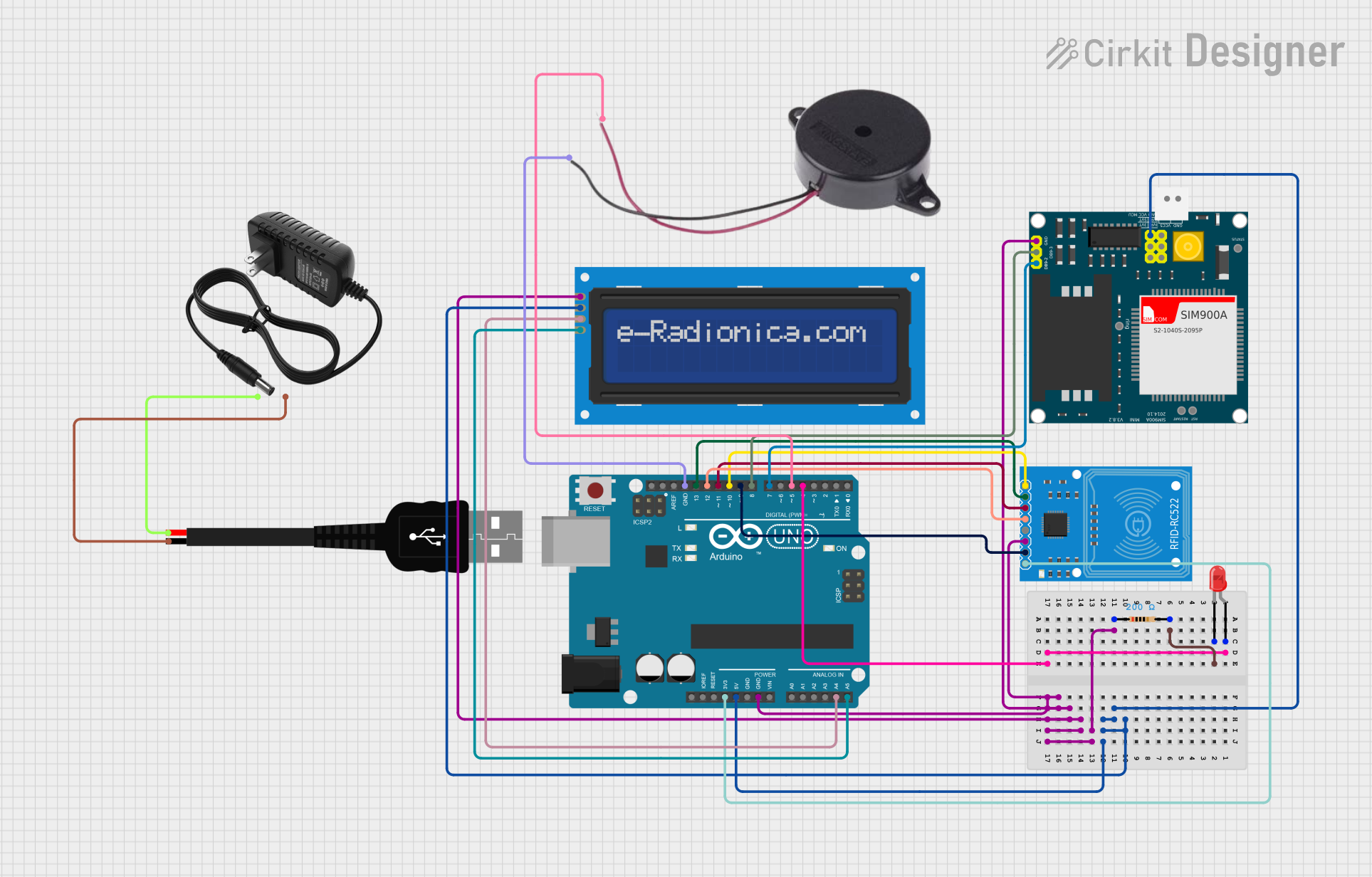
Circuit Documentation
Summary
The circuit in question is designed to interface an Arduino UNO with various peripherals including an LCD screen with I2C interface, an RFID-RC522 module, a red LED, a SIM900A GSM module, a buzzer, and a resistor. The circuit is powered by a 12V power supply, which also interfaces with a USB male 2-pin connection. The Arduino UNO's digital and analog pins are used to control and communicate with the connected devices. The circuit is intended for applications that require RFID reading, GSM communication, user feedback through an LCD and a buzzer, and status indication via an LED.
Component List
Arduino UNO
- Microcontroller board based on the ATmega328P
- It has 14 digital input/output pins, 6 analog inputs, a 16 MHz quartz crystal, a USB connection, a power jack, an ICSP header, and a reset button.
LCD screen 16x2 I2C
- A 16 character by 2 line display with an I2C interface
- It has pins for SCL, SDA, VCC, and GND.
RFID-RC522
- An RFID reader/writer module
- It has pins for SDA, SCK, MOSI, MISO, IRQ, GND, RST, and 3.3V.
LED: Two Pin (red)
- A basic red LED with an anode and cathode pin.
SIM900A
- A GSM/GPRS module
- It has pins for GND, RXD, TXD, 5V, 3VR, 5VR, 3VT, 5VT, VCC, Ring, RESTART, RESET, and STATUS.
Resistor
- A passive two-terminal electrical component with a resistance of 200 Ohms.
Buzzer
- An electromechanical component that produces sound
- It has pins for POSITIVE and NEGATIVE.
12v power supply
- A power source that provides 12V output
- It has pins for positive (+) and negative (-) terminals.
USB male 2 pin connection
- A USB connector with two pins for power (Positive +) and ground (Negative -).
Wiring Details
Arduino UNO
- D4 connected to the anode of the red LED
- 5V connected to the VCC of the LCD screen and SIM900A
- GND connected to the GND of the LCD screen, RFID-RC522, SIM900A, and the cathode of the red LED through a resistor
- 3.3V connected to the 3.3V of the RFID-RC522
- A4 (SDA) connected to the SDA of the LCD screen
- A5 (SCL) connected to the SCL of the LCD screen
- D13 connected to the SCK of the RFID-RC522
- D12 connected to the MISO of the RFID-RC522
- D11 connected to the MOSI of the RFID-RC522
- D10 connected to the SDA of the RFID-RC522
- D9 connected to the RST of the RFID-RC522
- D8 connected to the RXD of the SIM900A
- D7 connected to the TXD of the SIM900A
- D5 connected to the POSITIVE of the buzzer
LCD screen 16x2 I2C
- SCL connected to A5 of the Arduino UNO
- SDA connected to A4 of the Arduino UNO
- VCC connected to 5V of the Arduino UNO
- GND connected to GND of the Arduino UNO
RFID-RC522
- SDA connected to D10 of the Arduino UNO
- SCK connected to D13 of the Arduino UNO
- MOSI connected to D11 of the Arduino UNO
- MISO connected to D12 of the Arduino UNO
- IRQ not connected
- GND connected to GND of the Arduino UNO
- RST connected to D9 of the Arduino UNO
- 3.3V connected to 3.3V of the Arduino UNO
LED: Two Pin (red)
- Anode connected to D4 of the Arduino UNO
- Cathode connected to one end of the resistor
SIM900A
- GND connected to GND of the Arduino UNO
- RXD connected to D8 of the Arduino UNO
- TXD connected to D7 of the Arduino UNO
- VCC connected to 5V of the Arduino UNO
Resistor
- One end connected to the cathode of the red LED
- The other end connected to GND of the Arduino UNO
Buzzer
- POSITIVE connected to D5 of the Arduino UNO
- NEGATIVE connected to GND of the Arduino UNO
12v power supply
- Positive (+) connected to Positive + of the USB male 2 pin connection
- Negative (-) connected to Negative - of the USB male 2 pin connection
Documented Code
Arduino UNO Code (sketch.ino)
void setup() {
  // put your setup code here, to run once:

}

void loop() {
  // put your main code here, to run repeatedly:

}
Additional Notes
- The code provided for the Arduino UNO is a template with empty setup and loop functions. The actual functionality needs to be implemented based on the requirements of the application.
- The SIM900A module requires a level shifter or voltage divider since it operates at 2.8V logic levels, which is not directly compatible with the 5V logic of the Arduino UNO.
- The RFID-RC522 operates at 3.3V, which is provided by the Arduino UNO.
- The LCD screen is interfaced via I2C, which simplifies the wiring and conserves Arduino pins for other uses.
- The red LED is connected with a current-limiting resistor to prevent damage to the LED.
- The buzzer is directly driven by a digital pin of the Arduino UNO, which can be toggled to produce sound.