Cirkit Designer
Your all-in-one circuit design IDE
Home /
Project Documentation
BC547 Transistor-Based Piezo Buzzer Circuit
Circuit Documentation
Summary of the Circuit
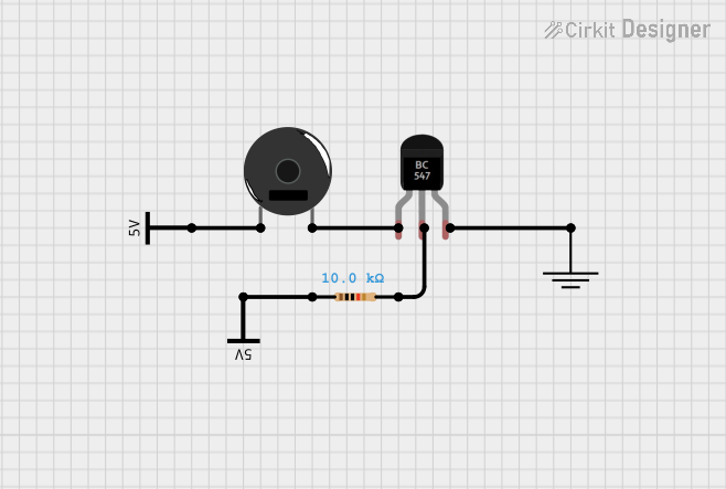
This circuit appears to be a simple buzzer system that is controlled by a BC547 transistor. The transistor acts as a switch to control the current flow to the piezo buzzer. A resistor is included in the circuit to limit the base current of the transistor. The circuit is powered by a Vcc source, and the emitter of the transistor is connected to the ground (GND).
Component List
BC547 Transistor
- Description: A general-purpose NPN bipolar junction transistor (BJT) used for switching and amplification.
- Pins: Collector, Base, Emitter
Piezo Buzzer
- Description: An electronic device that emits a tone when an electric signal is applied.
- Pins: pin 1, pin 2
Resistor
- Description: A passive two-terminal electrical component that implements electrical resistance as a circuit element.
- Properties: 10,000 Ohms resistance
- Pins: pin1, pin2
GND (Ground)
- Description: A reference point in an electrical circuit from which voltages are measured, a common return path for electric current, or a direct physical connection to the Earth.
- Pins: GND
Vcc (Power Supply)
- Description: Represents the positive supply voltage connection that powers the circuit.
- Pins: Vcc
Wiring Details
BC547 Transistor
- Collector is connected to pin 2 of the Piezo Buzzer.
- Base is connected to pin2 of the Resistor.
- Emitter is connected to GND.
Piezo Buzzer
- pin 1 is connected to Vcc.
- pin 2 is connected to the Collector of the BC547 Transistor.
Resistor
- pin1 is connected to Vcc.
- pin2 is connected to the Base of the BC547 Transistor.
GND (Ground)
- GND is connected to the Emitter of the BC547 Transistor.
Vcc (Power Supply)
- One Vcc is connected to pin 1 of the Piezo Buzzer.
- Another Vcc is connected to pin1 of the Resistor.
Documented Code
There is no microcontroller code provided for this circuit. If a microcontroller is to be included in the future, the code section will be updated accordingly to control the transistor and, by extension, the piezo buzzer.