
Arduino UNO-Based AC Light Dimmer with Potentiometer Control and LCD Display
View and Edit Project In Cirkit Designer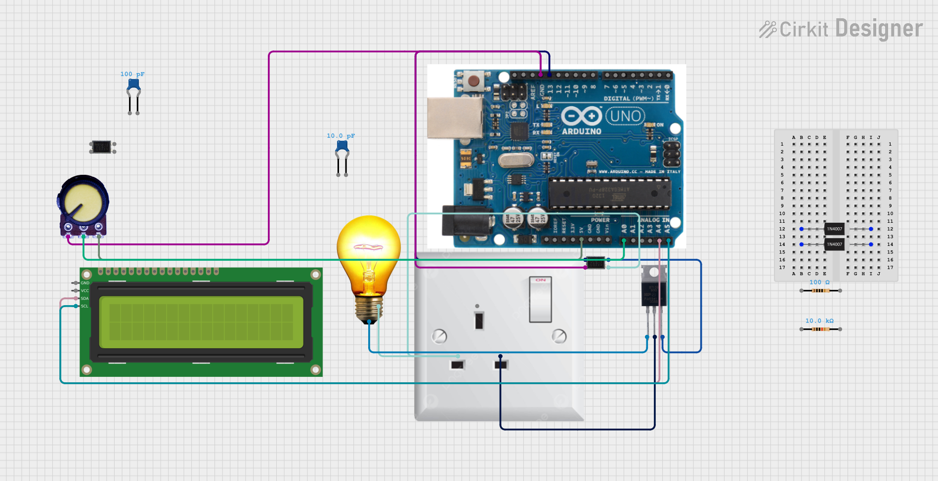
Circuit Documentation
Summary
This circuit is a light dimmer that controls the brightness of an AC bulb using a TRIAC. The brightness is adjusted via a potentiometer. The circuit includes an optocoupler for isolation and a zero-crossing detector for phase control. An Arduino UNO microcontroller is used to manage the control logic, and an I2C LCD is used to display the brightness level.
Component List
Arduino UNO
- Description: Microcontroller board based on the ATmega328P.
- Pins: SDA, AREF, GND, 13, 12, 11, 10, 9, 8, 7, 6, 5, 4, 3, 2, 1, 0, A5, A4, A3, A2, A1, A0, Vin, 5V, 3.3V, RESET, IOREF, SCL
BT139 600
- Description: TRIAC used for switching AC loads.
- Pins: MT1, MT2, GATE
1N4007 Rectifier Diode
- Description: General-purpose rectifier diode.
- Pins: Cathode, Anode
Resistor (100 Ohms)
- Description: Resistor with a resistance of 100 Ohms.
- Pins: pin1, pin2
Resistor (10k Ohms)
- Description: Resistor with a resistance of 10k Ohms.
- Pins: pin1, pin2
Potentiometer
- Description: Variable resistor used to adjust the brightness.
- Pins: GND, Output, VCC
Ceramic Capacitor (100pF)
- Description: Capacitor with a capacitance of 100pF.
- Pins: pin0, pin1
Ceramic Capacitor (10pF)
- Description: Capacitor with a capacitance of 10pF.
- Pins: pin0, pin1
AC Bulb
- Description: AC bulb used as the load.
- Pins: P, N
Optocoupler
- Description: Provides electrical isolation between the microcontroller and the TRIAC.
- Pins: Anode, Cathode, Collector, Emitter
AC Wall Plug Point
- Description: Provides AC power to the circuit.
- Pins: E, N, L
16x2 I2C LCD
- Description: LCD display for showing the brightness level.
- Pins: GND, VCC, SDA, SCL
Wiring Details
Arduino UNO
- GND connected to Potentiometer GND and Optocoupler Cathode.
- Pin 13 connected to Optocoupler Anode.
- A5 connected to 16x2 I2C LCD SCL.
- A4 connected to 16x2 I2C LCD SDA.
- A0 connected to Potentiometer Output.
- 5V connected to Potentiometer VCC.
BT139 600
- MT1 connected to AC Bulb P.
- MT2 connected to AC Wall Plug Point L.
- GATE connected to Optocoupler Collector.
1N4007 Rectifier Diode
- Cathode and Anode not connected in this circuit.
Resistor (100 Ohms)
- pin1 and pin2 not connected in this circuit.
Resistor (10k Ohms)
- pin1 and pin2 not connected in this circuit.
Potentiometer
- GND connected to Arduino UNO GND.
- Output connected to Arduino UNO A0.
- VCC connected to Arduino UNO 5V.
Ceramic Capacitor (100pF)
- pin0 and pin1 not connected in this circuit.
Ceramic Capacitor (10pF)
- pin0 and pin1 not connected in this circuit.
AC Bulb
- P connected to BT139 600 MT1.
- N connected to AC Wall Plug Point N and Optocoupler Emitter.
Optocoupler
- Anode connected to Arduino UNO Pin 13.
- Cathode connected to Arduino UNO GND.
- Collector connected to BT139 600 GATE.
- Emitter connected to AC Wall Plug Point N and AC Bulb N.
AC Wall Plug Point
- N connected to AC Bulb N and Optocoupler Emitter.
- L connected to BT139 600 MT2.
- E not connected in this circuit.
16x2 I2C LCD
- GND not connected in this circuit.
- VCC not connected in this circuit.
- SDA connected to Arduino UNO A4.
- SCL connected to Arduino UNO A5.
Code Documentation
/*
 * LIGHT DIMMER
 * This Arduino sketch controls the brightness of an AC bulb using a TRIAC.
 * The brightness is adjusted via a potentiometer. The circuit includes an
 * optocoupler for isolation and a zero-crossing detector for phase control.
 */

// Pin Definitions
#define TRIAC_PIN 13          // TRIAC trigger pin
#define ZC_PIN 2              // Zero-crossing detection pin
#define POT_PIN A0            // Potentiometer pin for control
#define LCD_SDA A4            // I2C LCD SDA pin
#define LCD_SCL A5            // I2C LCD SCL pin

// Variables
volatile int zeroCross = 0;
int firingDelay = 0;         // Delay to control phase angle
int dimming = 0;             // Dimming level (0-100)

#include <Wire.h>
#include <LiquidCrystal_I2C.h>

// Initialize the LCD
LiquidCrystal_I2C lcd(0x27, 16, 2);

void setup() {
  pinMode(TRIAC_PIN, OUTPUT);
  pinMode(ZC_PIN, INPUT);
  attachInterrupt(digitalPinToInterrupt(ZC_PIN), zeroCrossingISR, RISING);

  Serial.begin(9600);        // Debugging
  lcd.begin();
  lcd.backlight();
  lcd.setCursor(0, 0);
  lcd.print("Light Dimmer");
}

void loop() {
  // Read potentiometer value and map it to a firing delay
  int potValue = analogRead(POT_PIN);
  dimming = map(potValue, 0, 1023, 100, 0);  // Map to 0-100% brightness

  // Calculate delay based on dimming level
  firingDelay = (100 - dimming) * 65;  // Scale for 50Hz (use 78 for 60Hz)

  // Display dimming level on LCD
  lcd.setCursor(0, 1);
  lcd.print("Brightness: ");
  lcd.print(dimming);
  lcd.print("%");

  delay(100);  // Smooth dimming
}

// Interrupt Service Routine (ISR) for zero-crossing detection
void zeroCrossingISR() {
  zeroCross = 1;
  delayMicroseconds(firingDelay);  // Delay to control firing angle
  digitalWrite(TRIAC_PIN, HIGH);
  delayMicroseconds(10);           // Short pulse to trigger TRIAC
  digitalWrite(TRIAC_PIN, LOW);
}
This code controls the brightness of an AC bulb using a TRIAC. The brightness is adjusted via a potentiometer, and the current brightness level is displayed on an I2C LCD. The zero-crossing detection is used to control the phase angle for dimming the light.