Arduino-Controlled Robotic Vehicle with Ultrasonic Obstacle Avoidance
Circuit Documentation
Summary
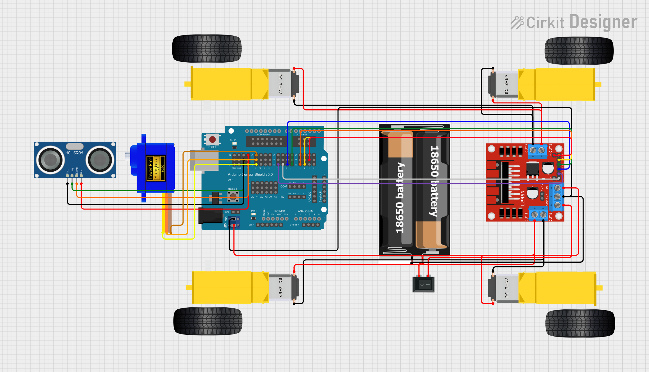
This circuit is designed to control a mobile robot equipped with ultrasonic sensors for distance measurement, DC gearmotors for movement, a servomotor for directional control, and a motor driver for motor management. The brain of the robot is an Arduino UNO, which interfaces with an Arduino Sensor Shield v5.0 for easy connection to various peripherals. The power is supplied by a 2x 18650 battery pack, and a rocker switch is used to control the power flow. The circuit's functionality is governed by embedded code that controls the motors based on the distance readings from the ultrasonic sensor.
Component List
Microcontroller
- Arduino UNO: A microcontroller board based on the ATmega328P, with a variety of digital and analog I/O pins.
Sensors
- HC-SR04 Ultrasonic Sensor: A sensor that measures distance by emitting ultrasonic waves and measuring the time taken for the echo to return.
Actuators
- Gearmotor DC Wheels (left and right): Motors that provide movement to the robot's wheels.
- Servomotor SG90: A small rotary actuator that controls the angular position, typically used for precise positioning.
Motor Driver
- L298N DC motor driver: A dual H-bridge motor driver that allows for the control of two DC motors simultaneously in either direction.
Power Supply
- 2x 18650 Battery Pack: A rechargeable battery pack providing the necessary power to the circuit.
Additional Components
- Rocker Switch (SPST): A single-pole single-throw switch used to connect or disconnect the power supply.
- Arduino Sensor Shield v5.0: An expansion board that allows for easy connection of sensors and actuators to the Arduino UNO.
Wiring Details
HC-SR04 Ultrasonic Sensor
- VCC: Connected to the 5V output on the Arduino Sensor Shield.
- TRIG: Connected to a digital signal pin on the Arduino Sensor Shield.
- ECHO: Connected to a digital signal pin on the Arduino Sensor Shield.
- GND: Connected to the ground pin on the Arduino Sensor Shield.
Gearmotors
- PIN1 and PIN2 (left and right gearmotors): Connected to the output pins of the L298N motor driver.
Servomotor SG90
- SIG: Connected to a digital signal pin on the Arduino Sensor Shield.
- VCC: Connected to the 5V output on the Arduino Sensor Shield.
- GND: Connected to the ground pin on the Arduino Sensor Shield.
L298N DC Motor Driver
- OUT1, OUT2, OUT3, OUT4: Connected to the gearmotors.
- 12V: Connected to the rocker switch.
- GND: Connected to the ground of the battery pack and the Arduino Sensor Shield.
- 5V: Connected to the 5V output on the Arduino Sensor Shield.
- ENA, ENB, IN1, IN2, IN3, IN4: Connected to digital signal pins on the Arduino Sensor Shield for motor control.
Rocker Switch (SPST)
- Pin 1: Connected to the positive terminal of the battery pack.
- Pin 2: Connected to the 12V input of the L298N motor driver.
2x 18650 Battery Pack
- VCC: Connected to the rocker switch.
- GND: Connected to the ground of the L298N motor driver and the Arduino Sensor Shield.
Documented Code
#include <Servo.h>

volatile int IN1 = 11;
volatile int IN2 = 6;
volatile int IN3 = 5;
volatile int IN4 = 3;
volatile int rightDistance;
volatile int leftDistance;
Servo servo_4;

void left_side_forward(int speed) {
  analogWrite(IN1, speed * 0.92);
  analogWrite(IN2, 0);
}

void right_side_forward(int speed) {
  analogWrite(IN3, speed);
  analogWrite(IN4, 0);
}

void left_side_backward(int speed) {
  analogWrite(IN1, 0);
  analogWrite(IN2, speed * 0.92);
}

void right_side_backward(int speed) {
  analogWrite(IN3, 0);
  analogWrite(IN4, speed);
}

float checkdistance_A1_A2() {
  digitalWrite(A1, LOW);
  delayMicroseconds(2);
  digitalWrite(A1, HIGH);
  delayMicroseconds(10);
  digitalWrite(A1, LOW);
  float distance = pulseIn(A2, HIGH) / 58.00;
  delay(10);
  return distance;
}

void forward(int speed) {
  left_side_forward(speed);
  right_side_forward(speed);
}

void backward(int speed) {
  left_side_backward(speed);
  right_side_backward(speed);
}

void left(int speed, int time) {
  left_side_backward(speed);
  right_side_forward(speed);
  delay(time);
  stop();
}

void right(int speed, int time) {
  left_side_forward(speed);
  right_side_backward(speed);
  delay(time);
  stop();
}

void stop() {
  left_side_forward(0);
  right_side_forward(0);
}

void setup() {
  servo_4.attach(4);
  pinMode(A1, OUTPUT);
  pinMode(A2, INPUT);
  pinMode(IN1, OUTPUT);
  pinMode(IN2, OUTPUT);
  pinMode(IN3, OUTPUT);
  pinMode(IN4, OUTPUT);
}

void loop() {
  servo_4.write(90);
  delay(200); // Reduce delay for better responsiveness

  float distance = checkdistance_A1_A2();
  while (distance > 15) {
    forward(150); // Increase speed for faster response
    distance = checkdistance_A1_A2(); // Continuously update distance
  }
  stop();
  delay(100); // Reduce delay for better responsiveness

  servo_4.write(0);
  delay(200); // Reduce delay for better responsiveness
  rightDistance = checkdistance_A1_A2();

  servo_4.write(180);
  delay(200); // Reduce delay for better responsiveness
  leftDistance = checkdistance_A1_A2();

  if (rightDistance >= leftDistance) {
    right(200, 300); // Reduce rotation time for more precision
  } else {
    left(200, 300); // Reduce rotation time for more precision
  }
}
This code is designed to run on the Arduino UNO microcontroller. It includes functions for moving the robot forward, backward, left, and right, as well as stopping the robot. The checkdistance_A1_A2 function is used to measure the distance from the HC-SR04 ultrasonic sensor. The main loop controls the robot's movement based on the distance measurements, making decisions to turn left or right depending on the distance to obstacles.