Arduino UNO Controlled Time Display and LED Indicator System
Circuit Documentation
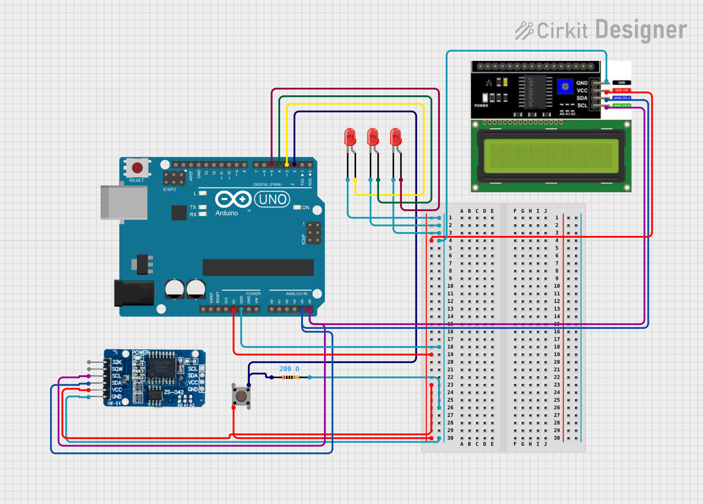
Summary
This document provides a detailed overview of a circuit that includes a microcontroller (Arduino UNO), a real-time clock (RTC DS3231), an LCD I2C display, multiple LEDs, a pushbutton, and a resistor. The circuit is designed to interface with various components through digital and analog pins on the Arduino UNO, which serves as the central processing unit. The RTC provides timekeeping functionality, while the LCD display offers a user interface. The LEDs are used as indicators, and the pushbutton serves as an input device. The resistor is used to limit current in the circuit.
Component List
Pushbutton
- Description: A standard pushbutton with four pins, typically used as an input device to trigger events in a circuit.
Resistor
- Description: A passive two-pin component used to limit the current flow in the circuit.
- Value: 200 Ohms
Arduino UNO
- Description: A microcontroller board based on the ATmega328P, equipped with a variety of digital and analog pins for interfacing with other components.
RTC DS3231
- Description: A highly accurate I2C real-time clock with an integrated temperature-compensated crystal oscillator (TCXO) and crystal.
LED: Two Pin (red)
- Description: A two-pin light-emitting diode (LED) that emits red light when powered.
LCD I2C Display
- Description: A liquid crystal display that communicates with the microcontroller via the I2C protocol, used for displaying text and numbers.
Wiring Details
Pushbutton
- Pins:
- Pin 3 (out) connected to Arduino UNO D2
- Pin 2 (in) connected to 5V power rail
Resistor
- Pins:
- Pin 1 connected to Arduino UNO D2
- Pin 2 connected to the common ground rail
Arduino UNO
- Pins:
- GND connected to the common ground rail
- 5V connected to the 5V power rail
- D2 connected to Pushbutton Pin 3 (out) and Resistor Pin 1
- D3 connected to LED anode
- D4 connected to LED anode
- D5 connected to LED anode
- A4 (SDA) connected to LCD I2C Display SDA and RTC DS3231 SDA
- A5 (SCL) connected to LCD I2C Display SCL and RTC DS3231 SCL
RTC DS3231
- Pins:
- GND connected to the common ground rail
- VCC connected to the 5V power rail
- SDA connected to Arduino UNO A4 (SDA)
- SCL connected to Arduino UNO A5 (SCL)
LEDs
- Common Pins:
- Cathodes connected to the common ground rail
- Individual Pins:
- Anode of one LED connected to Arduino UNO D3
- Anode of another LED connected to Arduino UNO D4
- Anode of the third LED connected to Arduino UNO D5
LCD I2C Display
- Pins:
- GND connected to the common ground rail
- VCC connected to the 5V power rail
- SDA connected to Arduino UNO A4 (SDA)
- SCL connected to Arduino UNO A5 (SCL)
Documented Code
void setup() {
  // put your setup code here, to run once:

}

void loop() {
  // put your main code here, to run repeatedly:

}
Filename: sketch.ino
Note: The provided code is a template and does not contain any functional code. It is expected that the user will add the necessary setup and loop code to interact with the components in the circuit.