
Circuit Documentation
Summary
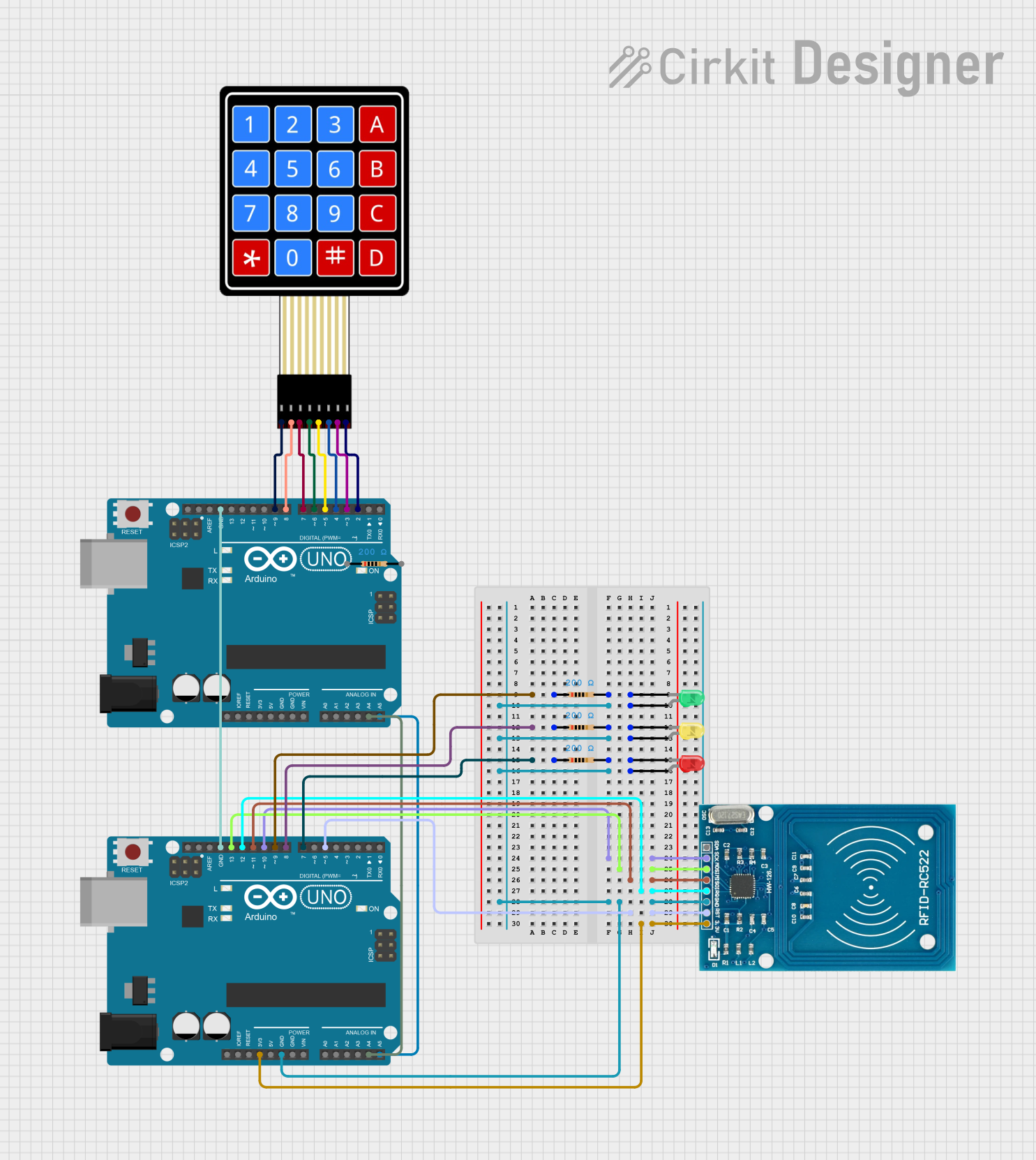
This circuit integrates two Arduino UNO microcontrollers with a variety of peripherals including an RFID-RC522 module, a 4x4 Membrane Matrix Keypad, and three LEDs (red, green, and yellow) each with a corresponding resistor. The Arduinos are interconnected and share common power and ground lines. The RFID module is connected to one of the Arduinos for communication over the SPI interface. The keypad is interfaced with the other Arduino through digital pins. Each LED is connected to a digital pin through a resistor, forming a simple current-limiting circuit.
Component List
Microcontrollers
- Arduino UNO: A microcontroller board based on the ATmega328P. It has 14 digital input/output pins, 6 analog inputs, a 16 MHz quartz crystal, a USB connection, a power jack, an ICSP header, and a reset button.
Input Devices
- RFID-RC522: An RFID reader/writer module that operates at 13.56 MHz. It communicates with a microcontroller over the SPI interface.
- 4X4 Membrane Matrix Keypad: A simple interface for user input, featuring 16 buttons arranged in a 4x4 grid.
Output Devices
- LED: Two Pin (red): A red light-emitting diode used as an indicator light.
- LED: Two Pin (green): A green light-emitting diode used as an indicator light.
- LED: Two Pin (yellow): A yellow light-emitting diode used as an indicator light.
Passive Components
- Resistor (200 Ohms): A resistor with a resistance of 200 Ohms, used to limit current to the LEDs.
Wiring Details
Arduino UNO
- Digital Pins (D2-D9): Connected to the 4x4 Membrane Matrix Keypad for button press detection.
- Analog Pins (A4, A5): Interconnected between the two Arduino UNO boards for potential I2C communication.
- SPI Pins (D10-D13): Connected to the RFID-RC522 module for SPI communication.
- Power (3.3V, 5V): Provide power to the RFID-RC522 module and the LEDs through resistors.
- Ground (GND): Common ground for the circuit.
RFID-RC522
- VCC (3.3V): Powered by the 3.3V output from one of the Arduino UNO boards.
- RST: Connected to a digital pin on the Arduino for reset control.
- SPI Interface (MISO, MOSI, SCK, IRQ): Connected to corresponding SPI pins on the Arduino for communication.
4X4 Membrane Matrix Keypad
- Rows (R1-R4) and Columns (C1-C4): Each row and column is connected to a unique digital pin on the Arduino for keypad scanning.
LEDs with Resistors
- Anode: Connected to the 5V power supply through a 200 Ohm resistor.
- Cathode: Connected to a digital pin on the Arduino for control.
Documented Code
Arduino UNO (Primary)
void setup() {
  // put your setup code here, to run once:

}

void loop() {
  // put your main code here, to run repeatedly:

}
Arduino UNO (Secondary)
void setup() {
  // put your setup code here, to run once:

}

void loop() {
  // put your main code here, to run repeatedly:

}
Note: The provided code is a template and does not include specific functionality. It should be expanded to initialize the connected devices and handle the desired logic for the circuit.