Cirkit Designer
Your all-in-one circuit design IDE
Home /
Project Documentation
Arduino-Controlled Quadcopter with GPS and NRF24L01 Wireless Communication
Circuit Documentation
Summary
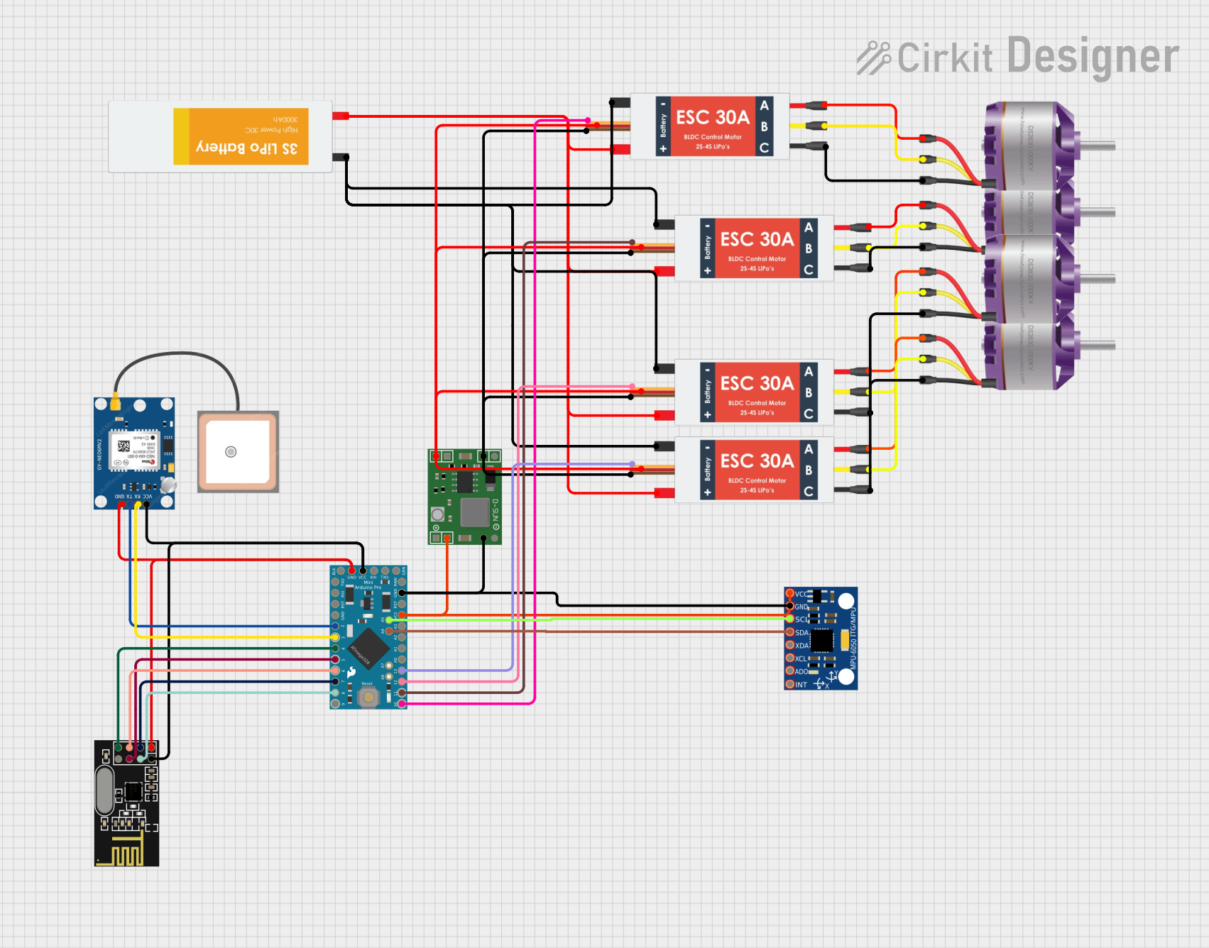
This document provides a detailed overview of a circuit designed to interface various components with an Arduino Pro Mini microcontroller. The circuit includes communication modules, power regulation, and motor control for brushless motors. The Arduino Pro Mini serves as the central processing unit, interfacing with a GPS module, an NRF24L01 wireless communication module, an MPU-6050 motion sensor, and four Electronic Speed Controllers (ESCs) connected to brushless motors. A Lipo battery provides power to the system, with a power regulator ensuring stable voltage for the sensitive components.
Component List
Arduino Pro Mini
- Microcontroller board based on the ATmega328
- Operates at 5V with a clock speed of 16MHz
- Features digital and analog I/O pins
NRF24L01
- 2.4GHz wireless transceiver module
- Utilizes SPI interface for communication
GPS NEO 6M
- GPS receiver module
- Provides location data via serial communication
MP1584EN Power Regulator Board
- Step-down (buck) converter
- Regulates input voltage to a stable output
Lipo Battery
- Rechargeable battery
- Provides power to the circuit
Electronic Speed Controller (ESC)
- Controls the speed of brushless motors
- Receives power from the battery and control signals from the microcontroller
MPU-6050
- Motion tracking device with a 3-axis gyroscope and a 3-axis accelerometer
- Communicates with the microcontroller via I2C
Brushless Motor
- Three-phase motor used for propulsion
- Controlled by the ESCs
Wiring Details
Arduino Pro Mini
- VCC connected to GPS NEO 6M, NRF24L01, and MPU-6050
- GND connected to GPS NEO 6M, NRF24L01, and MPU-6050
- A4 (SDA) connected to MPU-6050 SDA
- A5 (SCL) connected to MPU-6050 SCL
- D2 connected to GPS NEO 6M TX
- D3 connected to GPS NEO 6M RX
- D4 connected to NRF24L01 MISO
- D5 connected to NRF24L01 MOSI
- D6 connected to NRF24L01 SCK
- D7 connected to NRF24L01 CE
- D8 connected to NRF24L01 CSN
- SCK, MISO, MOSI, D10 connected to ESCs' Signal pins
NRF24L01
- VCC (3V) and GND connected to Arduino Pro Mini
- CSN connected to Arduino Pro Mini D8
- CE connected to Arduino Pro Mini D7
- SCK connected to Arduino Pro Mini D6
- MOSI connected to Arduino Pro Mini D5
- MISO connected to Arduino Pro Mini D4
GPS NEO 6M
- VCC and GND connected to Arduino Pro Mini
- RX connected to Arduino Pro Mini D3
- TX connected to Arduino Pro Mini D2
MP1584EN Power Regulator Board
- IN + and IN - connected to ESCs' 5v out and GND out, respectively
- OUT + and OUT - connected to MPU-6050 VCC and GND, respectively
Lipo Battery
- VCC and GND connected to all ESCs' Battery VCC and Battery GND, respectively
Electronic Speed Controller (ESC)
- Battery VCC and Battery GND connected to Lipo Battery
- Signal connected to Arduino Pro Mini (SCK, MISO, MOSI, D10)
- 5v out and GND out connected to MP1584EN Power Regulator Board IN + and IN -, respectively
- M1, M2, M3 connected to corresponding pins L1, L2, L3 of Brushless Motors
MPU-6050
- VCC and GND connected to MP1584EN Power Regulator Board OUT + and OUT -, respectively
- SDA connected to Arduino Pro Mini A4
- SCL connected to Arduino Pro Mini A5
Brushless Motor
- L1, L2, L3 connected to corresponding pins M1, M2, M3 of ESCs
Documented Code
Arduino Pro Mini Code (sketch.ino)
void setup() {
  // put your setup code here, to run once:

}

void loop() {
  // put your main code here, to run repeatedly:

}
Additional Notes
- The provided code is a template and does not contain any functional implementation.
- The user is expected to fill in the setup and loop functions with the desired logic to control the components connected to the Arduino Pro Mini.
- The code should initialize the communication interfaces (SPI for NRF24L01 and I2C for MPU-6050), configure the GPS module, and set up the ESCs for motor control.
- Proper safety checks and error handling should be implemented for reliable operation.